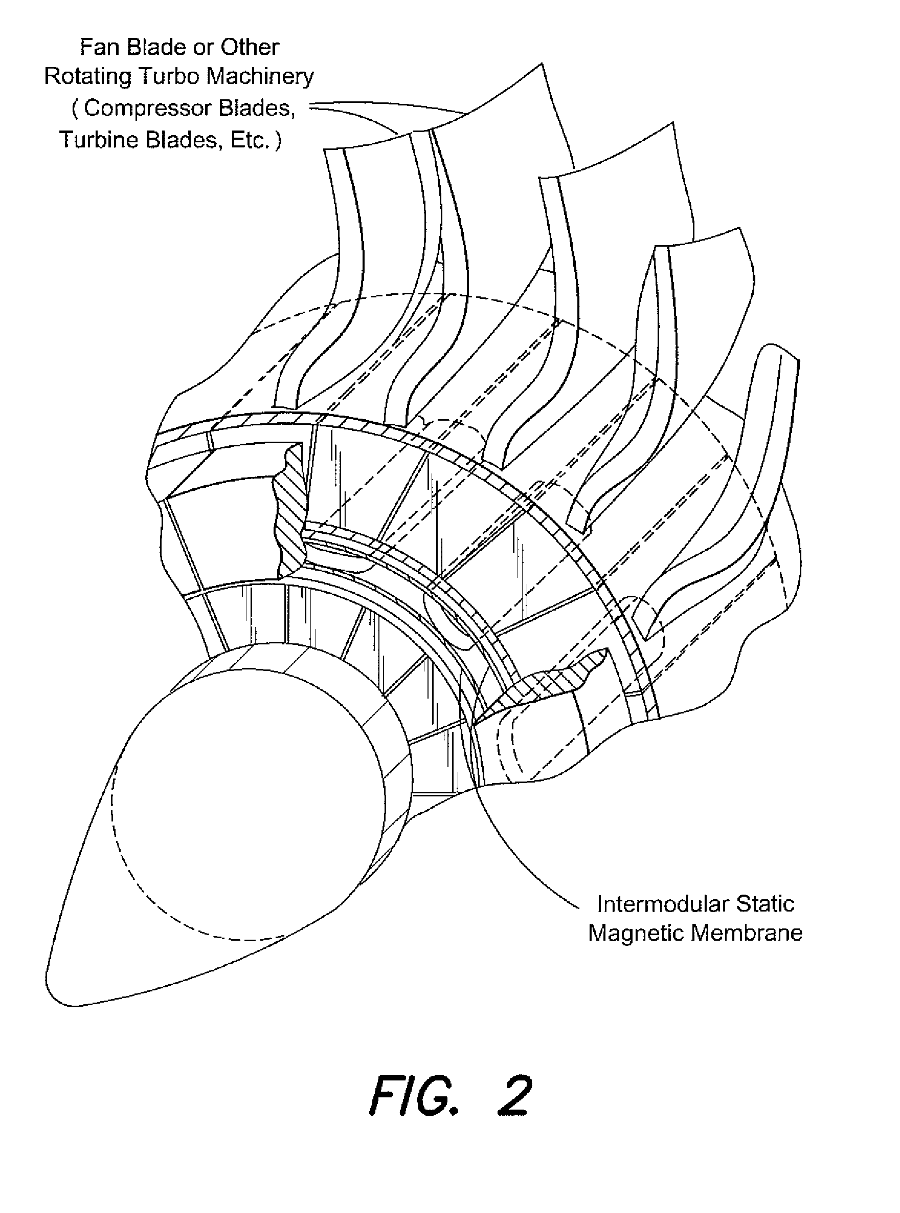
Magnetic advanced gas-turbine transmission with radial aero-segmented nanomagnetic-drive (MAGTRAN)

a nanomagnetic drive and advanced gas turbine technology, applied in the direction of dynamo-electric brake control, mechanical equipment, machines/engines, etc., can solve the problems of inability to define applications, inability to design nor innovate on utilizing knowledge, and inability to connect bypass fans to compressors to power turbines. achieve the effect of maximizing the thermodynamic extraction of kinetic energy and maximizing engine performan

Active Publication Date: 2013-05-21
SONIC BLUE AEROSPACE
View PDF8 Cites 42 Cited by
  • Summary
  • Abstract
  • Description
  • Claims
  • Application Information

AI Technical Summary

Benefits of technology

The patent describes an electromagnetic gas turbine engine transmission system that optimizes engine performance by running each stage at its own optimal design point speed. The bypass fan, compressors, power turbines, and turbines are segmented from each other and may counter rotate to maximize energy extraction. Magnetic load carrying capacity and magnetic torque behavior can be measured using various configurations. The electromagnetic transmission is associated with the magnetic field distribution between multiple poles arranged in stator and rotor configurations, ensuring the same behavior in each turbomachinery segment. The technical effect of the invention is improved engine performance through optimal design and minimization of mechanical contact and linkage between the transmission stages.

Problems solved by technology

No design nor innovation has been conducted on utilizing knowledge and the art of magnetic transmissions that operate at high speed to benefit the efficiency of aero gas turbine engines or differing power propulsion architecture.
The topology today of mechanically linked gas turbines to connect the bypass fan to compressor to the power turbine is very limited as all the stages of the compressor are connected together to one spool or more which is connected to the power turbine, hence driving the compressor.
These efforts resulted in torque density calculation at several different locations along the baseline of an experimental three-phase stator and rotor permanent magnet synchronous electrical machine demonstrating a quasi-static magnetic field for example, but this was not a high speed machine nor had the need for a variable torque in moderating the transfer of power.
No application has ever been done in defining innovative topologies for an electromagnetic segmented high torque density aero gas turbine engine transmission, nor defining operability requirements which drive design and topology of the electromagnetic structures.
Vibration problems are particularly serious in the machine transmission design when the forcing frequencies match one or more of the structural resonant frequencies in the machine.

Method used


Image

  • Magnetic advanced gas-turbine transmission with radial aero-segmented nanomagnetic-drive (MAGTRAN)
  • Magnetic advanced gas-turbine transmission with radial aero-segmented nanomagnetic-drive (MAGTRAN)
  • Magnetic advanced gas-turbine transmission with radial aero-segmented nanomagnetic-drive (MAGTRAN)

Examples


Embodiment Construction

[0035]An electrical machine apparatus having magnetic gearing embedded therein includes a moveable rotor having a first magnetic field associated therewith, a stator configured with a plurality of stationary stator windings therein, and a magnetic flux modulator interposed between the moveable rotor and the stator windings. The magnetic flux modulator is configured to transmit torque between the first magnetic field associated with the moveable rotor and a second magnetic field through a movable stator, through a plurality of magnetic flux gates arranged axially in the modulator with the field excited by, and controlled by, eddy currents normal to the field through the plurality of stationary stator magnets governed by the position of the modulator rotating in reference to the rotating (at different speeds, hence flux paths) stator and rotor and their magnetic field poles, than the speed of the modulator and its interfering referenced field poles, with the eddy currents existing flu...


PUM


Abstract

An electrical machine apparatus having magnetic gearing embedded therein includes a moveable rotor having a first magnetic field associated therewith, a stator configured with a plurality of stationary stator windings therein, and a magnetic flux modulator interposed between the moveable rotor and the stator windings. The magnetic flux modulator is configured to transmit torque between the first magnetic field associated with the moveable rotor and a second magnetic field through a movable stator, through a plurality of magnetic flux gates arranged axially in the modulator with the field excited by, and controlled by, eddy currents normal to the field through the plurality of stationary stator magnets governed by the position of the modulator rotating in reference to the rotating (at different speeds, hence flux paths) stator and rotor and their magnetic field poles, than the speed of the modulator and its interfering referenced field poles, with the eddy currents existing flux gate arrays with open or closing sequencing governing rotational speeds of the movable rotor, and enabling magnetic gear ratios, in respect to the driving movable stator, intermediate magnetic flux modulator, methods of a continuously variable, high torque, aero gas turbine transmission which allows for complete segmentation of turbomachinary stages (in respect to the bypass fan, compressor and power of the aero gas turbine.

Description

CROSS REFERENCE TO RELATED APPLICATIONS[0001]This application claims priority to the following:[0002]U.S. Provisional Application Ser. No. 61 / 294,189 filed Jan. 12, 2010, entitled MAGNETICALLY ADVANCED GEARED PROPELLER FOR ROTATIONALLY OPPOSITE PROP-FANS (MAGPROP); and[0003]U.S. Provisional Application Ser. No. 61 / 294,171 filed Jan. 12, 2010, entitled MAGNETIC ADVANCED GAS-TURBINE TRANSMISSION WITH RADIAL AERO-SEGMENTED NANOMAGNETIC-DRIVE (MAGTRAN),[0004]the disclosures of which are incorporated herein by this reference in their entirety for all purposes.FIELD OF THE INVENTION[0005]The disclosed concept relates to aircraft engines, and, more particularly, to a variable magnetic gear transmission.BACKGROUND[0006]Aero gas turbine engines are very high speed thermodynamic machines burning jet fuel for combustion with the high speed exhaust effluent (2500 to 3000 ft. / sec.) impinging on turbine blades, rotating them, and torque transferred with mechanical drive transmissions at the cente...

Claims


Application Information

Patent Timeline
Patent Type & Authority Patents(United States)
IPC IPC(8): H02K21/12
CPCH02K21/024H02K21/14F02C3/113F05D2260/404F05D2260/4041
Inventor LUGG, RICHARD H.
Owner SONIC BLUE AEROSPACE
Why Eureka
Try Eureka