
Multi-rate digital phase locked loop

a phase lock and multi-rate technology, applied in the field of digital phase lock loops, can solve the problems of dpll to consume an undesirable amount of power, quantization giving rise to quantization noise, and spectral purity of lo signal compromised to an unacceptable degree, so as to reduce the power consumption of dpll, reduce digital images, and improve sample rate

Inactive Publication Date: 2013-04-30
QUALCOMM INC
View PDF4 Cites 7 Cited by
  • Summary
  • Abstract
  • Description
  • Claims
  • Application Information

AI Technical Summary

Benefits of technology

The patent text describes a multi-rate DPLL (discontinuous phase lock loop) circuit that is designed to reduce power consumption and improve the image quality of digital images in a transmission system. The circuit operates at different sample rates for different parts of the system, such as the DCO (discontinuous cooled oscillator) and the TDC (tonic delay calibrator). By adjusting these sample rates, the circuit can reduce digital images and quantization noise in the output signal. This design also allows for more efficient power consumption compared to conventional DPLL circuits. In practical applications, the sample rate of the control circuitry can be adjusted based on the problem being addressed (e.g. reducing digital images or quantization noise). The patent text also describes a simplified version of the multi-rate DPLL circuit for use in a receiver system. Overall, the technical effect of this patent is to improve the quality and reduce the power consumption of digital images in transmission systems.

Problems solved by technology

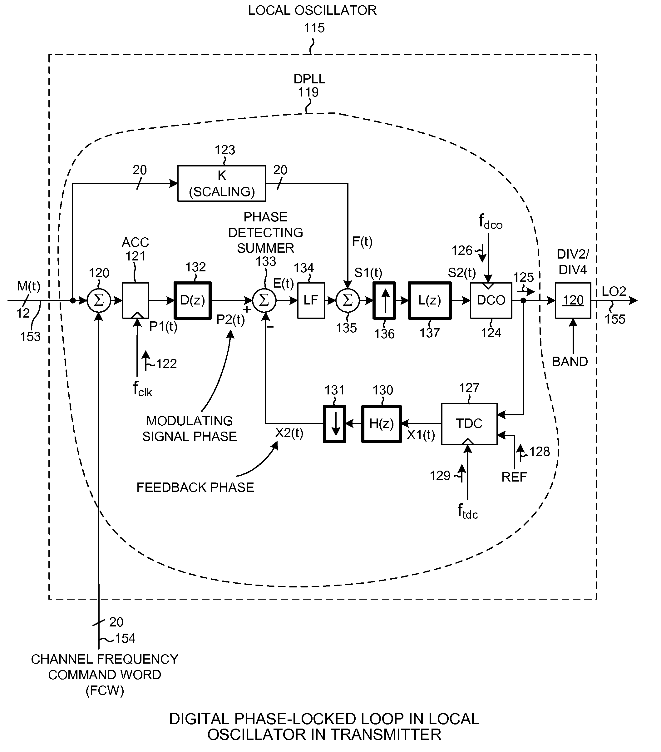
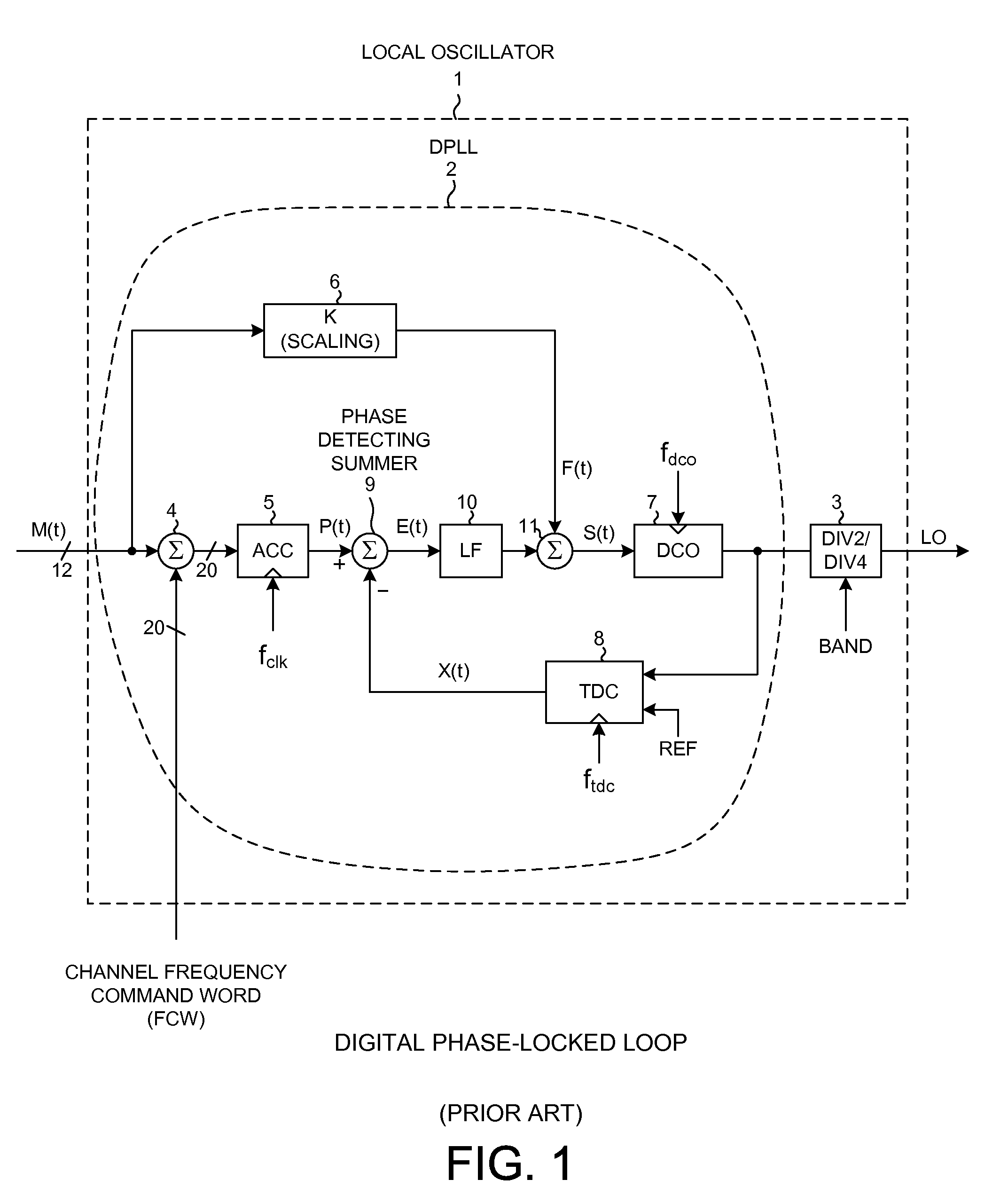
As DPLL 2 operates, TDC 8 quantizes the phase difference between edges of the DCO_OUT signal and corresponding edges of the REF signal, and this quantization gives rise to quantization noise.
If there is too much quantization noise, then the spectral purity of the LO signal is compromised to an unacceptable degree.
Unfortunately, running DPLL 2 at these high rates can cause the DPLL to consume an undesirably large amount of power.

Method used


Image

  • Multi-rate digital phase locked loop
  • Multi-rate digital phase locked loop
  • Multi-rate digital phase locked loop

Examples


Embodiment Construction

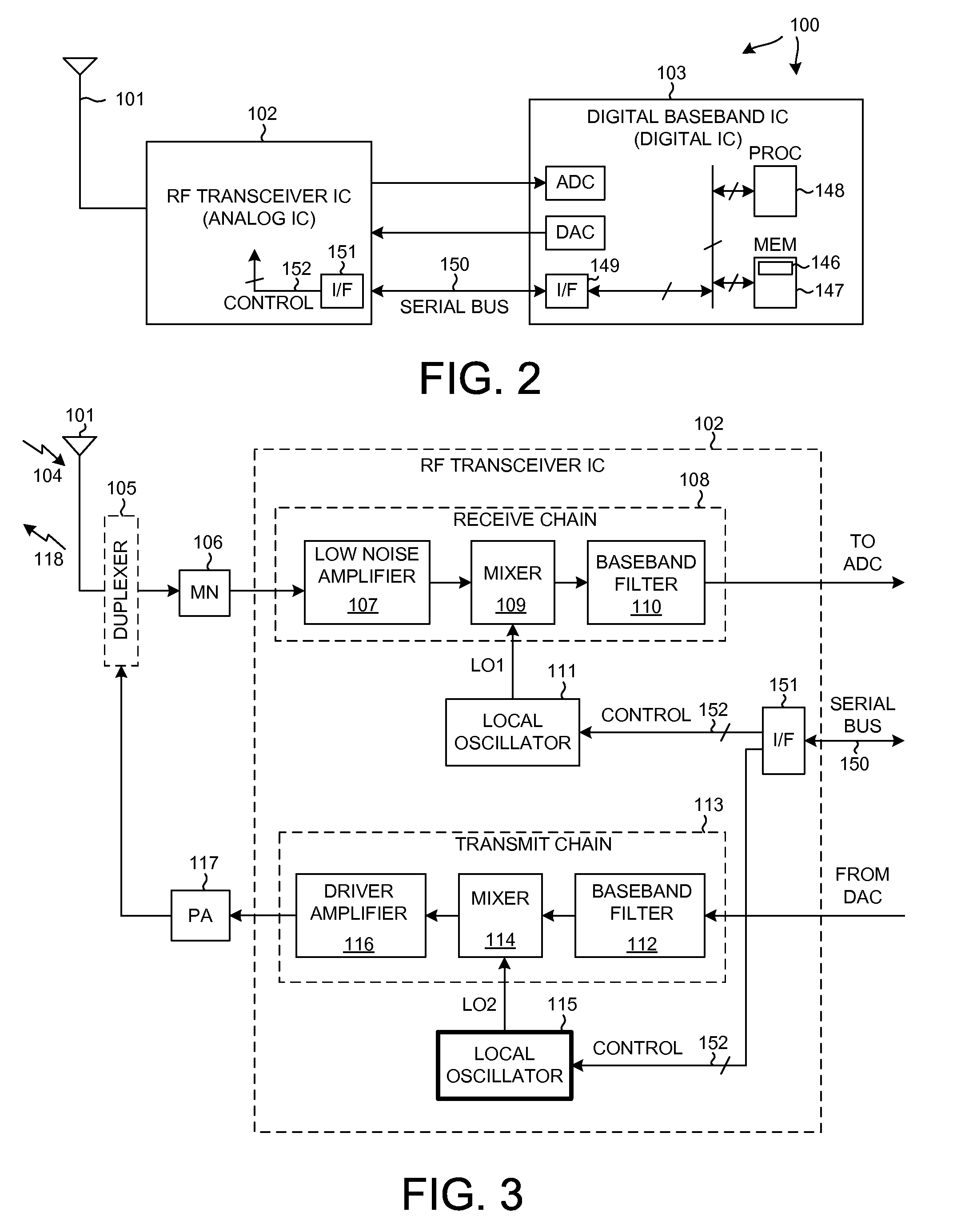
[0025]FIG. 2 is a very simplified high level block diagram of a mobile communication device 100 such as a cellular telephone. Device 100 includes (among other parts not illustrated) an antenna 101 usable for receiving and transmitting cellular telephone communications, an RF transceiver integrated circuit 102, and a digital baseband integrated circuit 103.

[0026]FIG. 3 is a more detailed diagram of the RF transceiver integrated circuit 102 of FIG. 1. In one very simplified explanation of the operation of the cellular telephone, if the cellular telephone is being used to receive audio information as part of a cellular telephone conversation, then an incoming transmission 104 is received on antenna 101. The signal passes through duplexer 105 and a matching network 106 and is amplified by a Low Noise Amplifier (LNA) 107 of a receive chain 108. After being downconverted in frequency by a mixer 109 and after being filtered by baseband filter 110, the information is communicated to the dig...


PUM


Abstract

A Digital Phase-Locked Loop (DPLL) involves a Time-to-Digital Converter (TDC) that receives a Digitally Controlled Oscillator (DCO) output signal and a reference clock and outputs a first stream of digital values. The TDC is clocked at a high rate. Downsampling circuitry converts the first stream into a second stream. The second stream is supplied to a phase detecting summer of the DPLL such that a control portion of the DPLL can switch at a lower rate to reduce power consumption. The DPLL is therefore referred to as a multi-rate DPLL. A third stream of digital tuning words output by the control portion is upsampled before being supplied to the DCO so that the DCO can be clocked at the higher rate. In a receiver application, no upsampling is performed and the DCO is clocked at the lower rate.

Description

BACKGROUND INFORMATION[0001]1. Technical Field[0002]The disclosed embodiments relate to Digital Phase-Locked Loops (DPLLs).[0003]2. Background Information[0004]FIG. 1 (Prior Art) is a block diagram of a type of local oscillator 1 that sees use in generating a Local Oscillator (LO) signal within a radio transmitter. The LO may, for example, be supplied to a mixer in a transmit chain of the transmitter such that a baseband signal is upconverted in frequency for later transmission. Local oscillator 1 includes a Digital Phase-Locked Loop (DPLL) 2 followed by a programmable divider 3. DPLL 2 implements two-point modulation so that the PLL output can be modulated faster than the PLL loop bandwidth. An incoming modulating signal M(t) is provided to both a low pass modulation path and to a high pass modulation path. M(t) may, for example, be a stream of twelve-bit digital values. In the low pass modulation path, a digital summer 4 receives the modulating signal M(t) along with a relatively ...

Claims


Application Information

Patent Timeline
Patent Type & Authority Patents(United States)
IPC IPC(8): H03D3/24
CPCH03L7/08H03C3/0941H03C3/095H03L2207/50H03C3/0966H03C3/09
Inventor BALLANTYNE, GARY JOHNGENG, JIFENGFILIPOVIC, DANIEL F.
Owner QUALCOMM INC
Learn More