Super capacitor for high power

a super capacitor and high-power technology, applied in the direction of fixed capacitors, fixed capacitor details, electrochemical generators, etc., can solve the problems of conventional super capacitors not being used in high-power fields, capacity deterioration may occur, etc., to increase contact area and reduce equivalent series resistance

Active Publication Date: 2013-03-05
SAMHWA CAPACITOR
View PDF9 Cites 4 Cited by
  • Summary
  • Abstract
  • Description
  • Claims
  • Application Information

AI Technical Summary

Benefits of technology

[0014]An aspect of the present invention provides a high power super capacitor that may increase a contact area without decreasing an area of an electrode active material layer, and may decrease an equivalent series resistance by forming a conductive connection member using electric energy.
[0015]Another aspect of the present invention also provides a high power super capacitor that may enhance the current distribution effect by increasing a contact area without decreasing an area of an electrode active material layer and may decrease a power loss, and may also enhance an exothermic characteristic by decreasing an equivalent series resistance, thereby being applicable to a high power field.
[0016]Another aspect of the present invention also provides a high power super capacitor that may employ a bobbin when winding an electrode assembly in a jellyroll type and thereby making it easier to wind the electrode assembly and maintaining durability, and may more easily and firmly insert a plug into the bobbin.

Problems solved by technology

Due to a decrease in an area of an electrode active material layer, a capacity deterioration may occur.
When decreasing the number of contact areas, the conventional super capacitor may not be employed in a high power field due to an increase in the power loss or the exothermic characteristic.

Method used


Image

  • Super capacitor for high power
  • Super capacitor for high power
  • Super capacitor for high power

Examples


Embodiment Construction

[0028]Reference will now be made in detail to exemplary embodiments of the present invention, examples of which are illustrated in the accompanying drawings, wherein like reference numerals refer to the like elements throughout. Exemplary embodiments are described below to explain the present invention by referring to the figures.

[0029]Hereinafter, embodiments of a high power super capacity according to the present invention will be described with reference to the accompanying drawings.

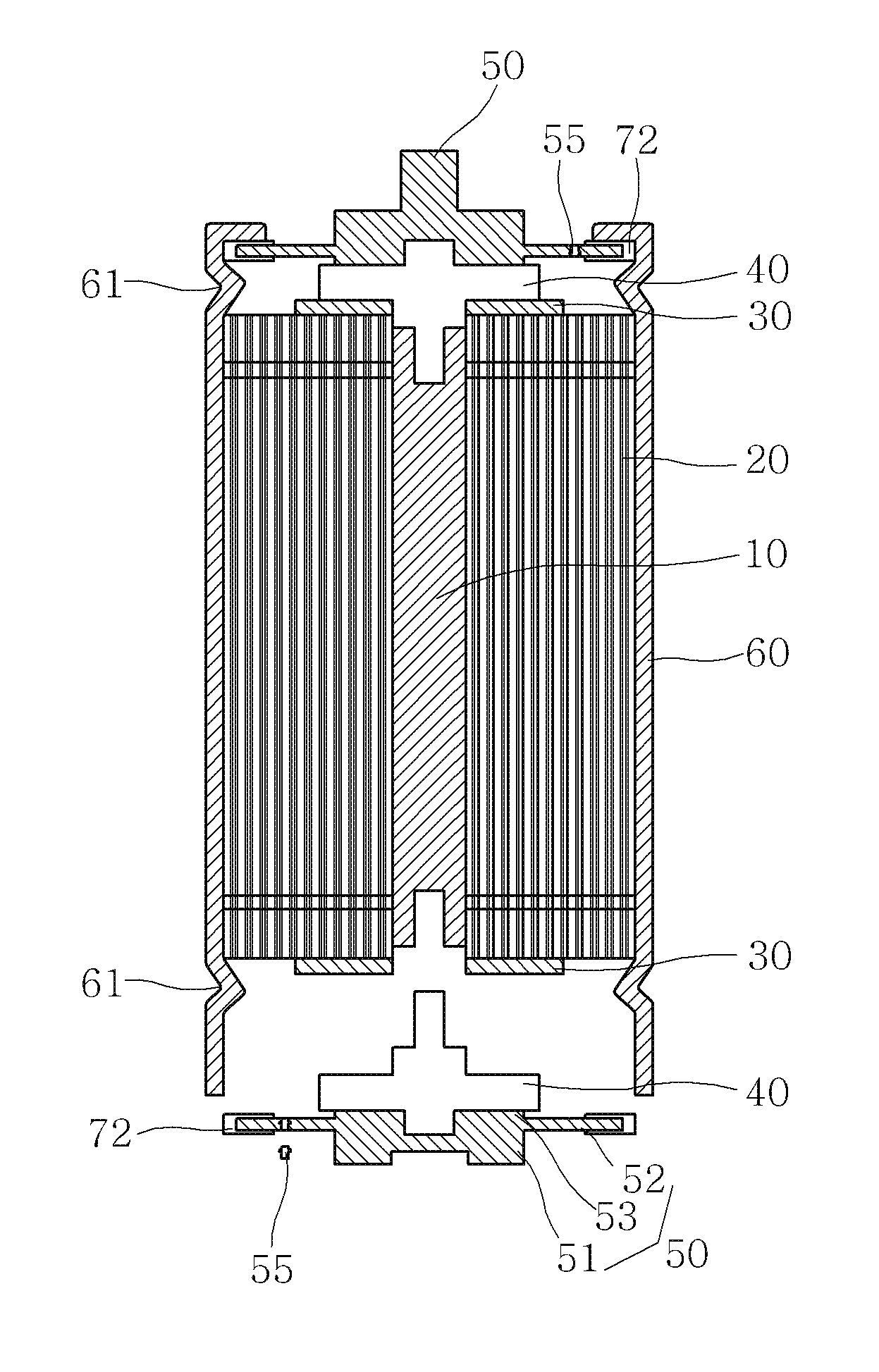
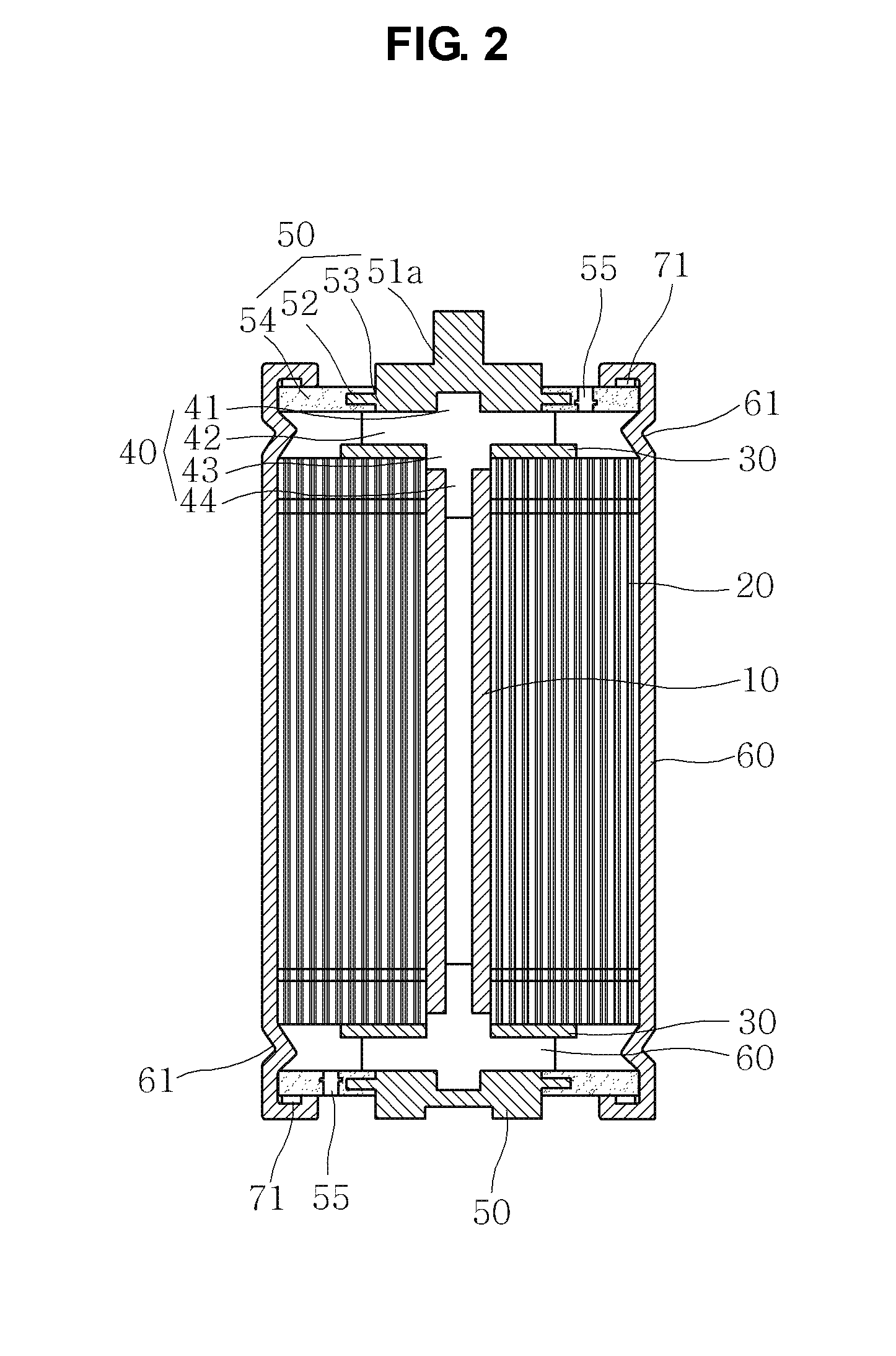
[0030]As shown in FIGS. 2 through 4, a high power super capacity according to an embodiment of the present invention includes a bobbin 10, an electrode assembly 20, a conductive connection member 30, and a plug 40. In the above configuration, the electrode assembly 20 is wound into the bobbin 10. Specifically, the electrode assembly 20 is wound into the bobbin 10 to be in a jellyroll type. The conductive connection member 30 is formed in each of one end and another end of the electrode assembly 20 usi...


PUM


Abstract

Provided is a high power super capacitor including: a bobbin; an electrode assembly being wound into the bobbin to be in a jellyroll type; a conductive connection member being formed in each of one end and another end of the electrode assembly using electric energy; and a plug being inserted into each of one end and another end of the bobbin, and being bonded with the conductive connection member using electric energy to be electrically connected to the electrode assembly. The electrode assembly may include a first electrode plate having a first polarity and including an inactive material area collector where the conductive connection member is formed in the one end of the electrode assembly, a second electrode plate having a second polarity and including another inactive material area collector where the conductive connection member is formed in the other end of the electrode assembly, and a separator being disposed between the first electrode plate and the second electrode plate to insulate between the first electrode plate and the second electrode plate. Accordingly, the high power super capacitor may increase a contact area without decreasing an area of electrode active material layer and may decrease an equivalent series resistance by forming a conductive connection member using electric energy, thereby enhancing an exothermic characteristic and being applied to a high power field.

Description

CROSS-REFERENCE TO RELATED APPLICATION[0001]This application claims the benefit of Korean Patent Application No. 10-2010-0026180, filed on Mar. 24, 2010 and Patent Application No. 10-2010-0048012, filed on May 24, 2010 in the Korean Intellectual Property Office, the disclosure of which is incorporated herein by reference.BACKGROUND OF THE INVENTION[0002]1. Field of the Invention[0003]The present invention relates to a high power super capacitor, and more particularly, to a high power super capacitor that may increase a contact area without decreasing an area of an electrode active material layer and may decrease an equivalent series resistance by forming a conductive connection member using electric energy.[0004]2. Description of the Related Art[0005]A super capacitor uses an electrode assembly of a jellyroll type. The electrode assembly of the jellyroll type may be manufactured by inserting a separator between a first electrode plate and a second electrode plate that are formed by ...

Claims


Application Information

Patent Timeline
Patent Type & Authority Patents(United States)
IPC IPC(8): H01G9/00
CPCH01G9/016H01G9/058H01G9/155H01G11/04H01G11/74H01G11/78H01G11/80Y02E60/13H01G11/22
Inventor OH, YOUNG JOOYOON, JUNG RAGLEE, KYUNG MINLEE, SANG WON
Owner SAMHWA CAPACITOR
Why Eureka
Try Eureka