
Magnetic connector

a technology of magnetic connectors and pins, applied in the direction of diagnostic recording/measuring, coupling device connections, diagnostics, etc., can solve the problems of high pin density and heavy demand on the connector mechanism, and achieve the effect of convenient disconnection

Active Publication Date: 2013-03-05
MASIMO CORP
View PDF30 Cites 572 Cited by
  • Summary
  • Abstract
  • Description
  • Claims
  • Application Information

AI Technical Summary

Benefits of technology

[0009]In various embodiments, at least one permanent magnet is embedded within one of the cores. If a permanent magnet is embedded within or near the anchor or near the air gap, then the permanent magnet locks the anchor within the air gap when the coil is de-energized. When the coil is energized, it creates an opposing field to the permanent magnet within the air gap so as to release the anchor. This permanent-magnet-based magnetic coupling holds the receptacle and plug together when the coil is de-energized, but allows the receptacle and plug to be easily disconnected by briefly energizing the coil.
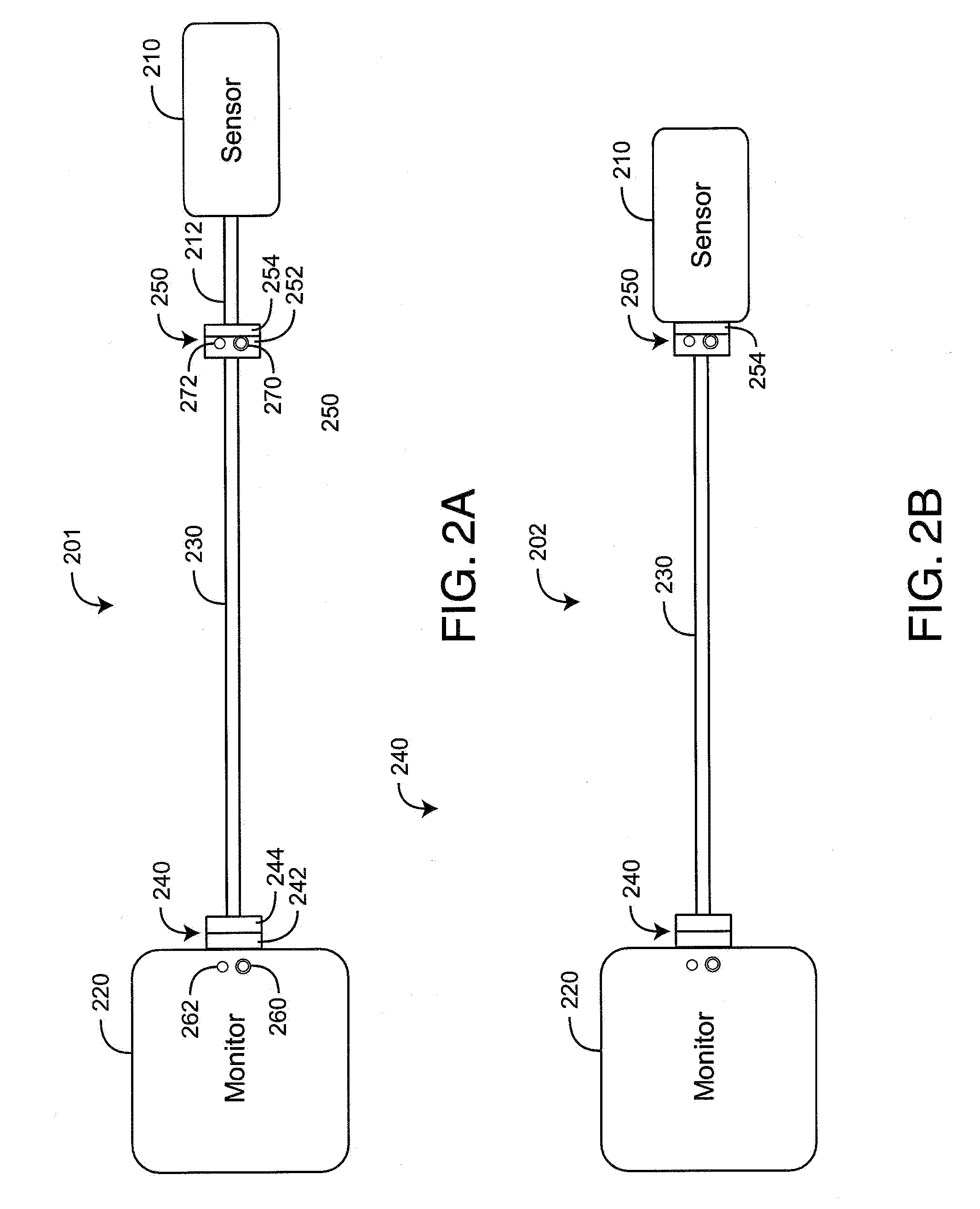
[0010]A further aspect of a magnetic connector is first and second magnetic elements having first and second contact sets. The first contact set is housed proximate the first magnetic element, and the second contact set is housed proximate the second magnetic element. At least one of the magnetic elements is responsive to a current input so as to alter a magnetic coupling between the magnetic elements. The magnetic coupling assists in making or breaking an electrical connection between the first and second contact sets. In an embodiment, the first magnetic element comprises a core of magnetically permeable material, a conductive coil having “N” turns disposed around at least a portion of the core, coil leads in communications with a current source and an air gap defined within the core. The current source has “I” amps energizing the coil so as to generate a electromagnetic field within the air gap proportional to N times I. In an embodiment, the second magnetic element comprises an anchor of magnetically permeable material sized to closely fit within the air gap. The contact sets make an electrical connection as the anchor is manually inserted into the air gap and break an electrical connection as the anchor is manually withdrawn from the air gap. The anchor locks within the air gap in response to a magnetic field within the air gap so as to maintain an electrical connection between the contact sets.

Problems solved by technology

This high pin density places a heavy demand on the connector mechanisms with respect to connect / disconnect ease, connection integrity, connector cost and life.

Method used


Image

  • Magnetic connector
  • Magnetic connector
  • Magnetic connector

Examples


first embodiment

[0034]As shown in FIG. 4A, in a first embodiment, the plug core 480 or at least the anchor 482 is a soft iron material and the switch 440 is normally closed (N.C.). Accordingly, D.C. current normally flows in the coil 420 and a magnetic field is maintained in the air gap 412. As such, the anchor 482 is attracted to and held within the air gap 412, locking the corresponding plug (not shown) to the corresponding receptacle (not shown). The switch 440 is actuated to interrupt the D.C. current, which releases the anchor 482 from the air gap 412 and allows the plug to be pulled from the receptacle.

second embodiment

[0035]As shown in FIG. 4B, in a second embodiment, the plug core 480 is a permanent magnet or is a material with a high magnetic permeability embedded with one or more permanent magnets 490. The permanent magnet field attracts the anchor 482 to the air gap 412, so as to lock a corresponding plug to a corresponding receptacle. The switch 440 is normally open (N.O.). Accordingly, actuating the switch 440 pulses the D.C. current to the coil 420, temporarily creating an opposing field (N), (S) within the air gap 412. This releases the anchor 482 from the air gap 412 and allows the plug to be pulled from the receptacle.

third embodiment

[0036]As shown in FIG. 4C, in a third embodiment, the plug core 480 is a soft iron material. One or more permanent magnets 460 are embedded within the receptacle core 410. The permanent magnet field attracts the anchor 482 to the air gap 412, so as to lock a corresponding plug to a corresponding receptacle. The switch 440 is normally open (N.O.). Accordingly, actuating the switch 440 pulses the D.C. current to the coil 420, temporarily creating an opposing field (N), (S) within the air gap 412. This releases the anchor 482 from the air gap 412 and allows the plug to be pulled from the receptacle.


PUM

PropertyMeasurementUnit
magnetic fieldaaaaaaaaaa
poweraaaaaaaaaa
infrared (IR) wavelengthaaaaaaaaaa

Abstract

A magnetic connector has a receptacle and a plug. The receptacle has an electromagnet comprising an inner core, an outer core, a coil disposed around the inner core and an air gap defined by the edges of the inner and outer cores. The plug has a plug core and an anchor defined by the plug core edge. The anchor is configured to insert into the air gap as a receptacle socket electrically connects with plug pins. The coil is energized and de-energized so as to assist in the insertion or removal of the anchor from within the air gap and the corresponding connection and disconnection of the socket and pins.

Description

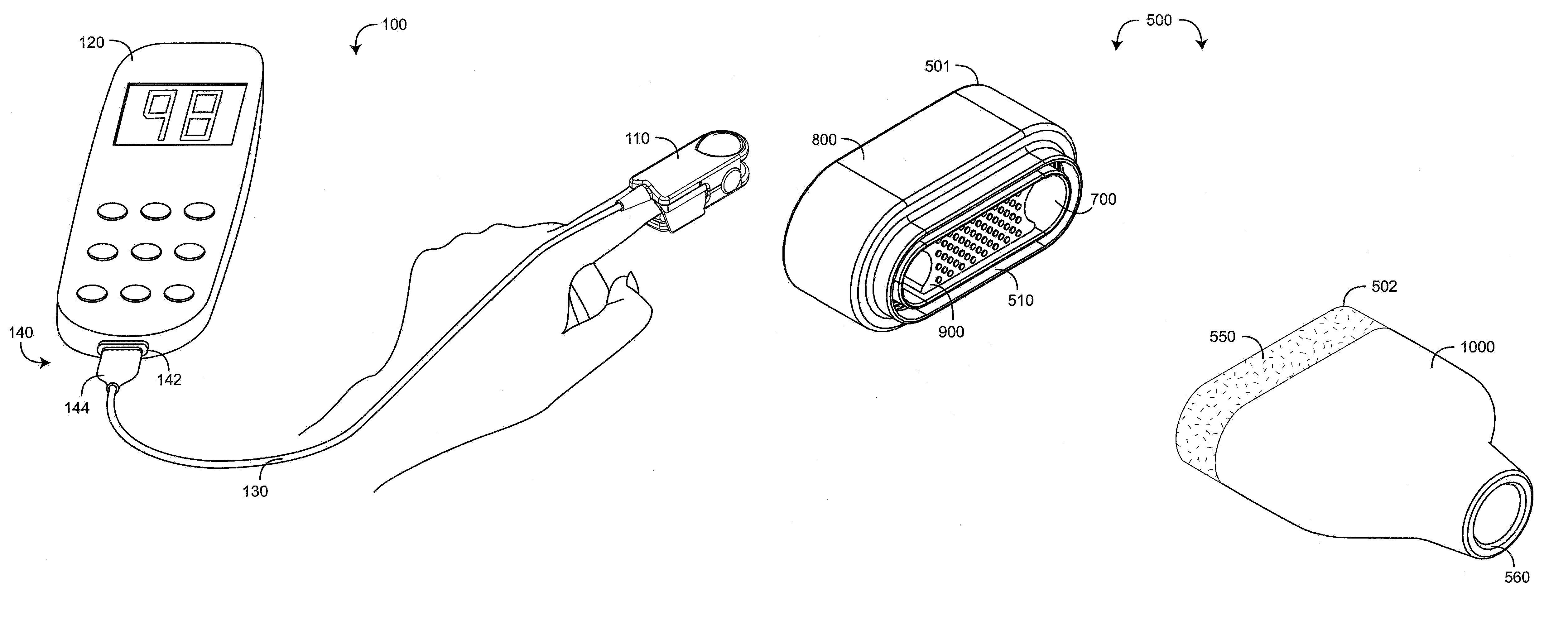
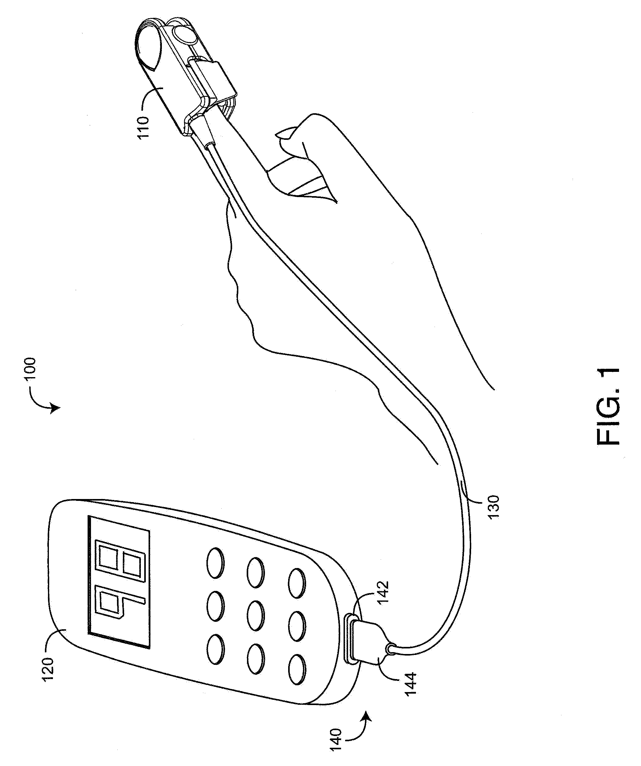
CROSS-REFERENCE TO RELATED APPLICATIONS[0001]The present application claims priority benefit under 35 U.S.C. §119(e) to U.S. Provisional Patent Application Ser. No. 61 / 159,336, filed Mar. 11, 2009, titled Magnetic Connector, hereby incorporated by reference herein.BACKGROUND OF THE INVENTION[0002]Noninvasive physiological monitoring systems for measuring constituents of circulating blood have advanced from basic pulse oximeters to monitors capable of measuring abnormal and total hemoglobin among other parameters. A basic pulse oximeter capable of measuring blood oxygen saturation typically includes an optical sensor, a monitor for processing sensor signals and displaying results and a cable electrically interconnecting the sensor and the monitor. A pulse oximetry sensor typically has a red wavelength light emitting diode (LED), an infrared (IR) wavelength LED and a photodiode detector. The LEDs and detector are attached to a patient tissue site, such as a finger. The cable transmits...

Claims


Application Information

Patent Timeline
Patent Type & Authority Patents(United States)
IPC IPC(8): H01R11/30
CPCH01R13/7037H01R13/6205H01R11/30H01R13/7175Y10T29/49117Y10S439/95H01R13/631A61B5/02055A61B5/14546A61B5/14551A61B5/6826H01R13/6591H01R2201/12
Inventor KIANI, MASSI JOE E.LAMEGO, MARCELO M.DALVI, CRISTIANOVO, HUNG THE
Owner MASIMO CORP
Learn More