
Ultrasonic diagnostic apparatus and ultrasonic diagnostic apparatus control method

a diagnostic apparatus and ultrasonic technology, applied in the field of ultrasonic diagnostic equipment, can solve the problems of difficult display, in real time or in a short time, and significantly decrease the efficiency of inspection, and achieve the effect of short tim

Active Publication Date: 2013-02-26
TOSHIBA MEDICAL SYST CORP
View PDF11 Cites 4 Cited by
  • Summary
  • Abstract
  • Description
  • Claims
  • Application Information

AI Technical Summary

Benefits of technology

[0014]The present invention has been made in view of such a conventional problem, and it is an object of the present invention to provide an ultrasonic diagnostic apparatus and an ultrasonic diagnostic apparatus control method capable of automatically correcting, in a short time, for example, the gain of volume data for a specimen relative to a voxel value in collecting the volume data.

Problems solved by technology

However, this method requires a new gain correction every change in the position or direction of a slice section (scan section) of the image data for a diagnostic part of the specimen, so that inspection efficiency significantly decreases, which has been a major problem particularly when ultrasound tests are conducted in a short time for a large number of specimens as in a screening test in, for example, a medical checkup.
It has therefore been difficult to display, in real time or in a short time, for example, three-dimensional image data based on the volume data which has subjected to the gain correction by the application of the above-mentioned methods.

Method used


Image

  • Ultrasonic diagnostic apparatus and ultrasonic diagnostic apparatus control method
  • Ultrasonic diagnostic apparatus and ultrasonic diagnostic apparatus control method
  • Ultrasonic diagnostic apparatus and ultrasonic diagnostic apparatus control method

Examples


Embodiment Construction

[0026]Hereinafter, an embodiment of the present invention will be described with reference to the drawing. It is to be noted that about the same signs are assigned to components having the same function and configuration in the following description and that a repetitive explanation is only given when necessary.

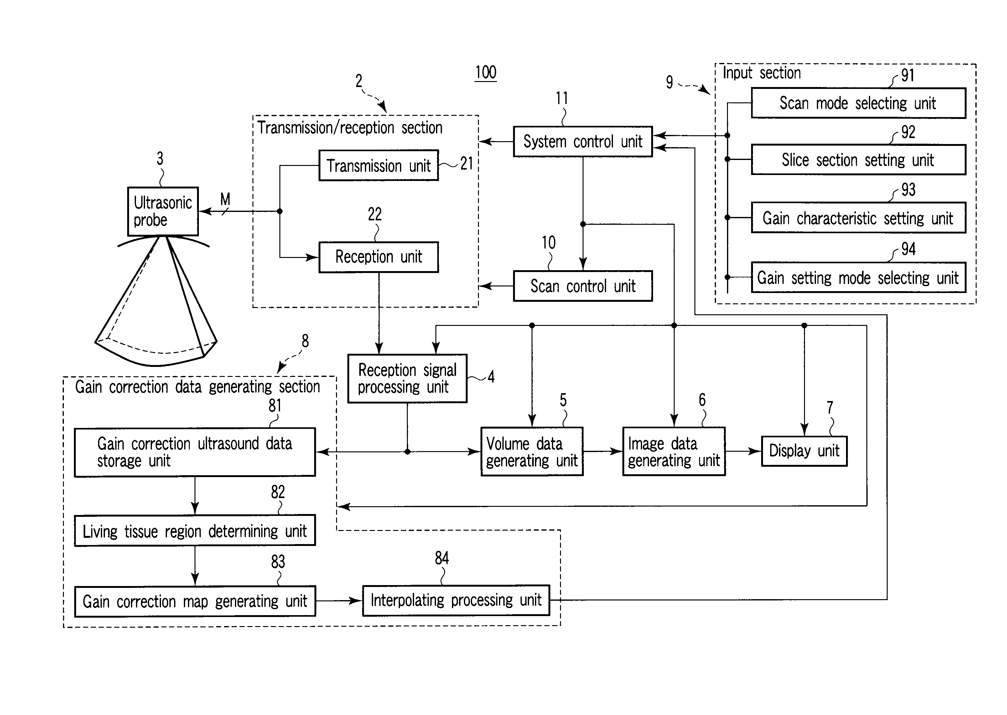
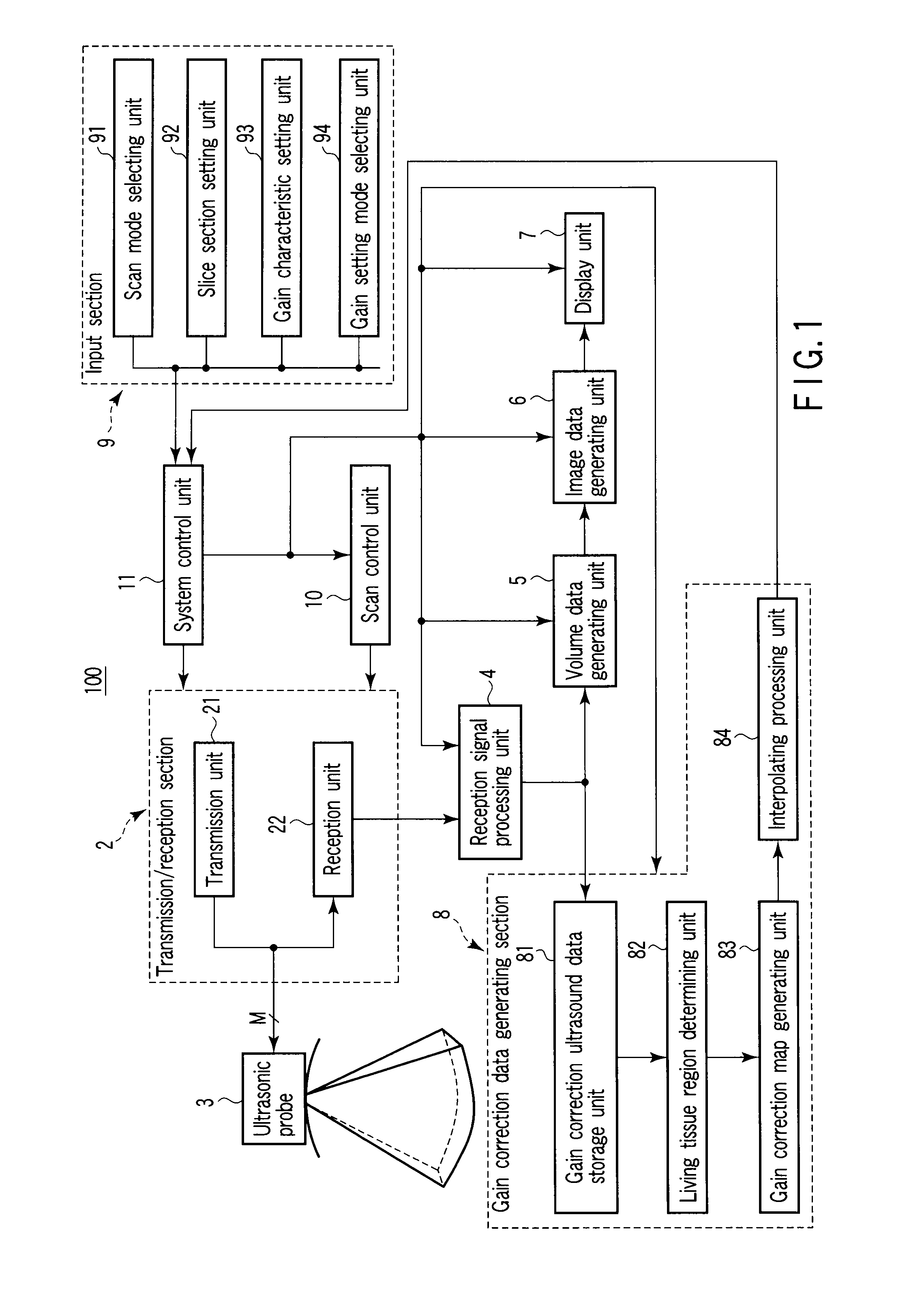
[0027]In the embodiment of the present invention described below, a first normal ultrasound data (biological data) in a plurality of predetermined slice sections and second ultrasound data (noise data) obtained without any transmission / reception of ultrasonic waves are collected in a gain correction scan mode intended for the generation of gain correction data for volume data collected from a specimen of interest, such that a diagnostic living tissue region is determined on the basis of the S / N of obtained from the difference between the biological data and the noise data and on the basis of the dispersion value of the biological data in each of a plurality of first regions s...


PUM


Abstract

A living tissue region determining unit of a gain correction data generating section determines a diagnostic living tissue region on the basis of an S / N and a dispersion value of ultrasound data collected from each of a plurality of slice sections in a gain correction scan mode intended for the generation of gain correction data for volume data. A gain correction map generating unit applies a least squares method to the average value of the ultrasound data in a plurality of regions set by dividing the living tissue region into predetermined sizes, thereby generating two-dimensional gain correction maps. Then, an interpolating processing unit interpolates, in a slice direction, the gain correction map generated for each of the plurality of slice sections, and generates three-dimensional gain correction data corresponding to each voxel of the volume data.

Description

CROSS-REFERENCE TO RELATED APPLICATIONS[0001]This application is based upon and claims the benefit of priority from prior Japanese Patent Application No. 2007-099246, filed Apr. 5, 2007, the entire contents of which are incorporated herein by reference.BACKGROUND OF THE INVENTION[0002]1. Field of the Invention[0003]The present invention relates to an ultrasonic diagnostic apparatus, and more particularly, it relates to an ultrasonic diagnostic apparatus and an ultrasonic diagnostic apparatus control method capable of automatically setting a gain for a reception signal collected from a specimen.[0004]2. Description of the Related Art[0005]An ultrasonic diagnostic apparatus transmits and receives ultrasonic waves in a plurality of directions of a specimen using an ultrasonic probe in which a plurality of oscillating elements are arranged, and displays, on a monitor, image data generated on the basis of reflected waves obtained at the time. This apparatus enables a real-time observatio...

Claims


Application Information

Patent Timeline
Patent Type & Authority Patents(United States)
IPC IPC(8): A61B8/14
CPCA61B8/08G01S7/52033G01S7/52085G01S15/8925G01S15/8993A61B8/14A61B8/543
Inventor KAKEE, AKIHIRO
Owner TOSHIBA MEDICAL SYST CORP
Learn More