Tile for forming a ground power supply line

a ground power supply and power supply technology, applied in the direction of power supply line details, power rails, single contact pieces, etc., can solve the problems of poor diffusion of these vehicles, large volume of batteries, high cost, and high weight of batteries, and achieve the effect of simple and cost-effectiveness

Inactive Publication Date: 2013-02-05
FIAT GRP AUTOMOBILES
View PDF13 Cites 17 Cited by
  • Summary
  • Abstract
  • Description
  • Claims
  • Application Information

AI Technical Summary

Benefits of technology

[0011]It is the object of the present invention to provide an electrified road surface, which allows to simply and cost-effectively solve the aforementioned problems.

Problems solved by technology

The poor diffusion of these vehicles is substantially due to two factors: their limited autonomy (maximum values in the range between 100 and 200 km); and the battery recharging time (typically in the range from a few dozens of minutes to several hours).
Furthermore, the batteries have relatively large volumes and heavy weights and provide a much lower energy density than the current automotive chemical fuels.
Vehicle autonomy becomes substantially unlimited, and the battery recharging times are null (because the batteries are recharged while travelling).
The switching circuits, the live line and the ground line are buried, whereby this solutions requires long implementation times and high costs, in particular for excavating.
Moreover, the road lane where the electric power line is installed is reserved only to electric vehicles intended to pick up the electric current, i.e. it may not be used by all motor vehicles circulating on the road, especially because the conductive segments are carried by an insulating frame which protrudes from the top of the road surface.
At the same time, the wear caused by the sliding contact between the brushes and the conductive segments is relatively high, whereby the brushes need to be frequently replaced.

Method used


Image

  • Tile for forming a ground power supply line
  • Tile for forming a ground power supply line
  • Tile for forming a ground power supply line

Examples


Embodiment Construction

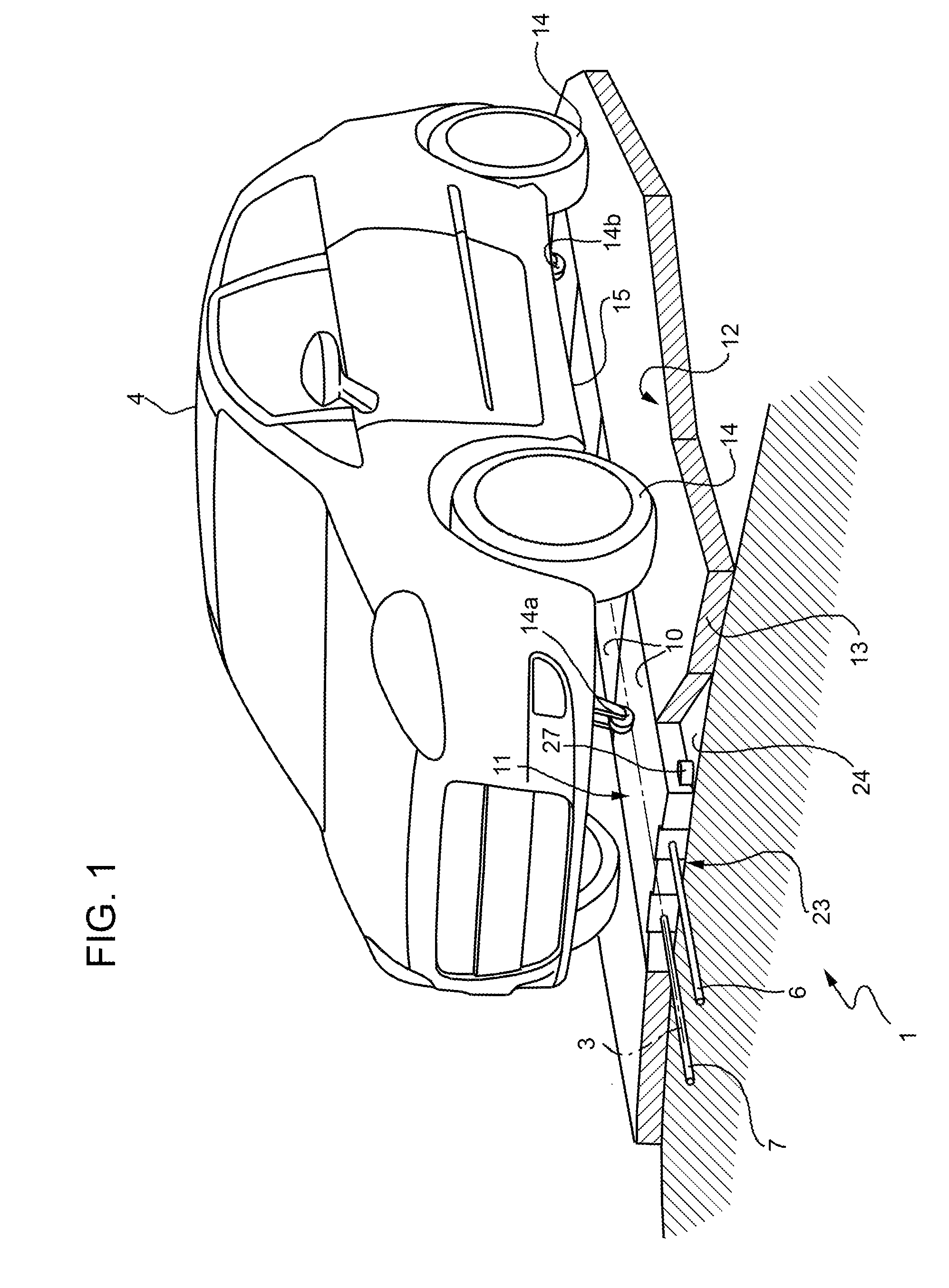
[0018]In FIG. 1, numeral 1 indicates as a whole a ground power supply line, which extends along a longitudinal direction 3, coinciding with a route or a road lane on which an electric traction vehicle 4 may travel.

[0019]Line 1 comprises a live conductor 6 and a ground conductor 7, which are parallel, are isolated from each other and are connected to the terminals of an electric power generator G (FIG. 4) arranged upstream of line 1 (and possibly defined by a connection box or an energy distribution station). Generator G is substantially isolated from ground; FIG. 4 shows two (high value) resistors Rg1 and Rg2, the purpose of which is only to avoid electrostatic potentials, and may also not be real (the normal losses of the energy distribution system may suffice).

[0020]Line 1 further comprises a series of conductive segments, which are defined by respective plates 10 aligned to one another along the direction 3, are electrically isolated from one another, and are also electrically is...


PUM


Abstract

A ground power supply line for electric traction vehicles is provided with two conductors carried by a series of tiles aligned to one another; each tile has a conductive plate and a lower supporting structure, which is made of insulating material and accommodates electric connectors, normally open switches, and a control and command unit, which switches the switches for selectively electrically connecting the conductive plate to the conductors in response to a signal deriving from an electric traction vehicle passing over said external conductive plate; the upper surface of the conductive plates is flushed with the remaining part of a road surface.

Description

[0001]The present invention relates to a tile for forming a ground power supply line, which allows electric traction vehicles to pick up electric current.BACKGROUND OF THE INVENTION[0002]Electric vehicles have always been of high interest in the field of low environmental impact mobility. The poor diffusion of these vehicles is substantially due to two factors: their limited autonomy (maximum values in the range between 100 and 200 km); and the battery recharging time (typically in the range from a few dozens of minutes to several hours).[0003]Furthermore, the batteries have relatively large volumes and heavy weights and provide a much lower energy density than the current automotive chemical fuels.[0004]In order to solve these drawbacks, it has been suggested to create an appropriate, fixed infrastructure capable of supplying electricity, which is picked up by the vehicle by means of appropriate conductive elements pressed against the ground. Thereby, the batteries are exclusively ...

Claims


Application Information

Patent Timeline
Patent Type & Authority Patents(United States)
IPC IPC(8): B60M1/34B60M1/08
CPCB60L5/42B60L11/1816B60M1/36B60M1/10Y02T10/7088Y02T90/121Y02T90/14Y02T10/7005Y02T10/70Y02T10/7072Y02T90/12
Inventor RE FIORENTIN, STEFANOCASELLATO, GIANCARLO
Owner FIAT GRP AUTOMOBILES
Why Eureka
Try Eureka