Eureka AIR delivers breakthrough ideas for toughest innovation challenges, trusted by R&D personnel around the world.

Data-processing system and data-processing method

a data processing system and data processing technology, applied in computing, instruments, climate sustainability, etc., can solve problems such as retransmission, and achieve the effect of simple power control at run-time and reduced power consumption of a shared data processing facility

Inactive Publication Date: 2013-01-29
NXP BV
View PDF7 Cites 1 Cited by
  • Summary
  • Abstract
  • Description
  • Claims
  • Application Information

AI Technical Summary

Benefits of technology

[0012]This has the advantage that the power consumption by a shared data-handling facility can be reduced to a lower level provided that it is sufficient to fulfill the requirements of the plurality of master data-processing devices and eventually one or more slave data-processing devices. Contrary to what is known the power consumption of the shared data-handling facility is not adapted to an individual requirement e.g. a processing speed of a processor or a bandwidth of a point-to-point communication link, but a to a set of devices that share the data-handling facility. The individual requirements from the data-processing devices may be aggregated in different ways, depending on the type of performance that is required.
[0016]The latter two embodiments allow a more easy characterization of the requirements towards the shared data-handling facility, because in these embodiments the requirements considered are more specific.
[0020]In an embodiment the data-processing facility comprises at least one monitor for monitoring an available performance of the data-handling facility towards a data-processing device and for comparing the available performance with the required performance, and wherein a difference between the available and the required performance is used to control the activity level of the data-handling facility. By monitoring the actually available performance offered by the data-handling facility to the individual data-processing devices the requirements of the data-processing devices can be more accurately met. Moreover, this embodiment allows the data processing devices to have mutually different types of requirements. For example if either of the monitors indicates that the requirement(s) of its data-processing devices is / are not met it will indicate to the aggregation facility that it requires an increased performance. As long as the aggregation facility receives one or more requests for improval of performance, regardless whether it is for latency or bandwidth for example, it will request the control unit to control the shared data-handling facility towards a higher activity level until all requirements are met. Alternatively the improval requests of the monitors may be weighted.
[0021]In an embodiment the data processing facility comprises at least one monitor for monitoring an available performance of the data-handling facility towards at least one data-processing device, the monitor comprising hardware facilities for recording at least one parameter selected from a maximum latency, a total latency, a total number of data units handled, and a general processing unit for reading said at least one parameter and calculating an aggregated performance from the at least one selected parameter. This embodiment has the advantage that on the one hand monitoring can be performed with a relatively low hardware requirements, as the parameters from which the at least one parameter is selected can be determined with relative simple hardware, such as adders and comparators. The more complicated calculations, such as divisions can be carried out by the general processing unit, which can be used also for other purposes. On the other hand this embodiment causes little overhead in communication as it suffices that the general processing unit only communicates with the hardware facilities at the start and the end of a monitoring time-frame.
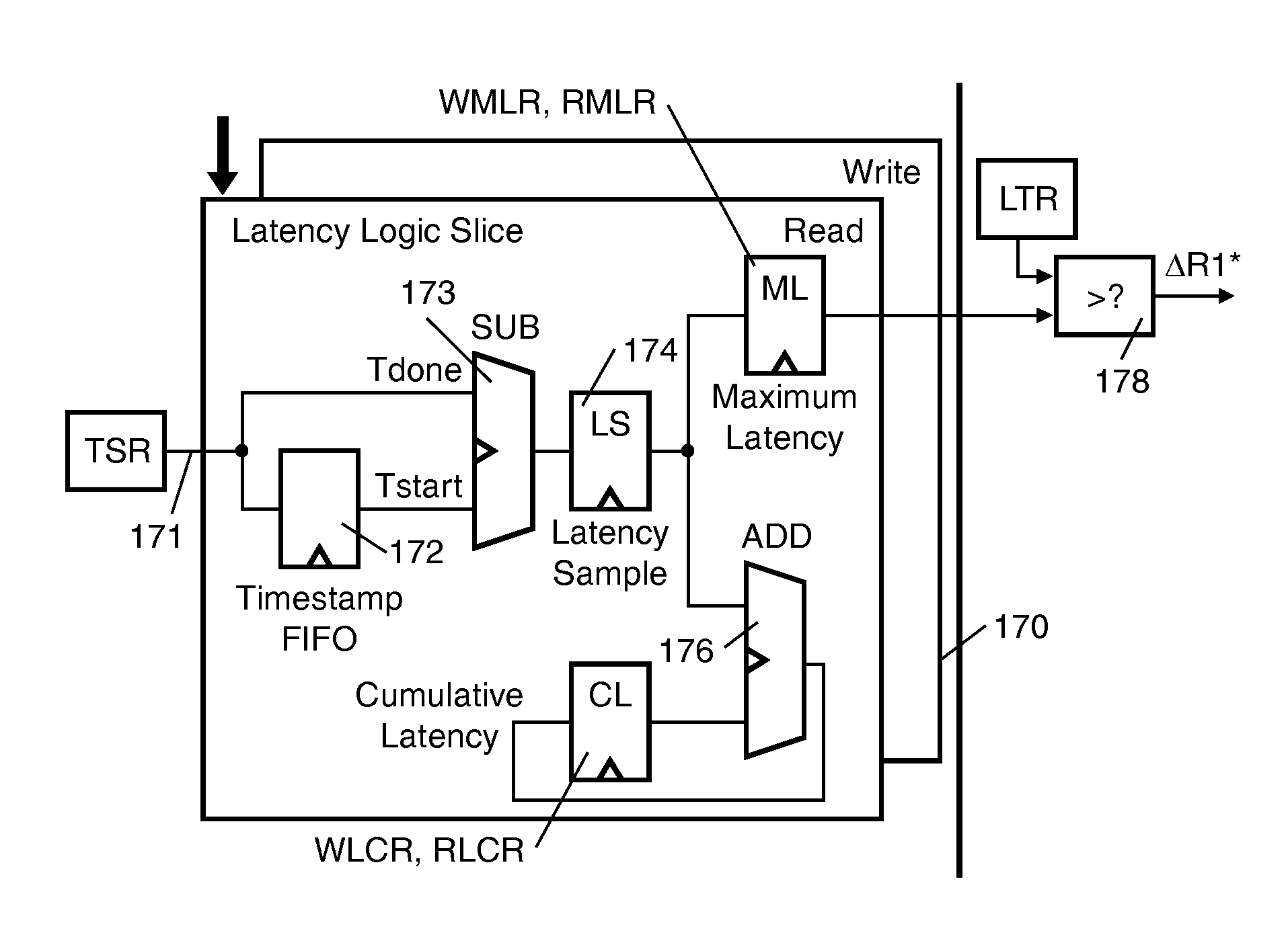
[0023]Such embodiment of the data processing facility may further comprise a latency tracking logic unit with a state machine and a plurality of counters, wherein the latency logic unit monitors a latency parameter for a selected processing device, and the counters count a number of data transactions for data processing devices not being monitored, wherein the state machine upon a request for monitoring for a different processing device prevents the FIFO from accepting further input from the time-stamp unit and flushes the FIFO step-wise upon execution of each request for which the point in time indication was stored in the FIFO and wherein the state machine allows the FIFO to accept point in time indications for the different processing device after the FIFO is flushed. This makes it possible to use a single monitor to subsequently observe the latency in the response of the shared data handling device towards different data processing devices.

Problems solved by technology

If transmitted encoded data has an irrecoverable error, a retransmission takes place.

Method used


Image

  • Data-processing system and data-processing method
  • Data-processing system and data-processing method
  • Data-processing system and data-processing method

Examples


second embodiment

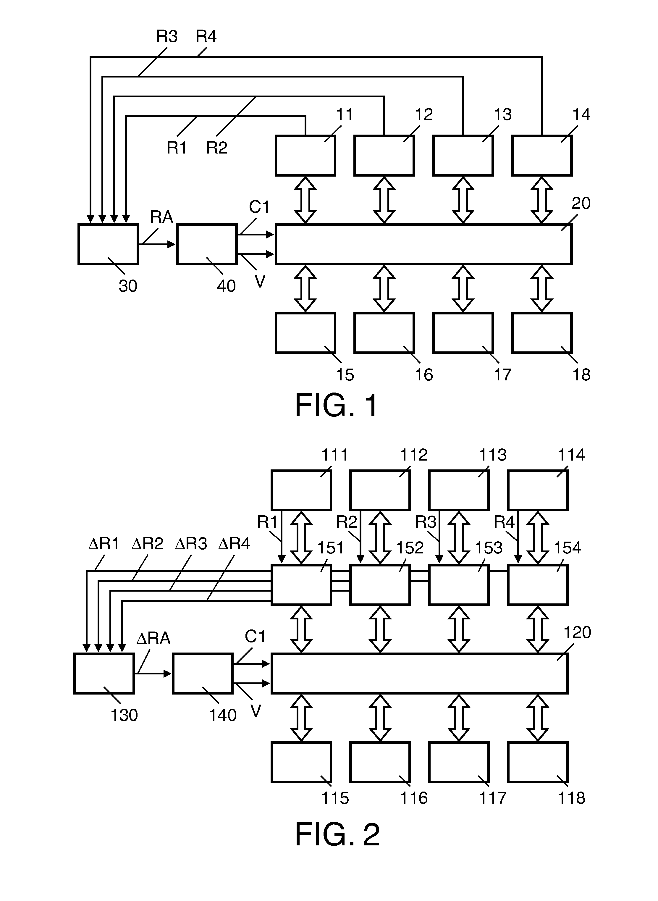
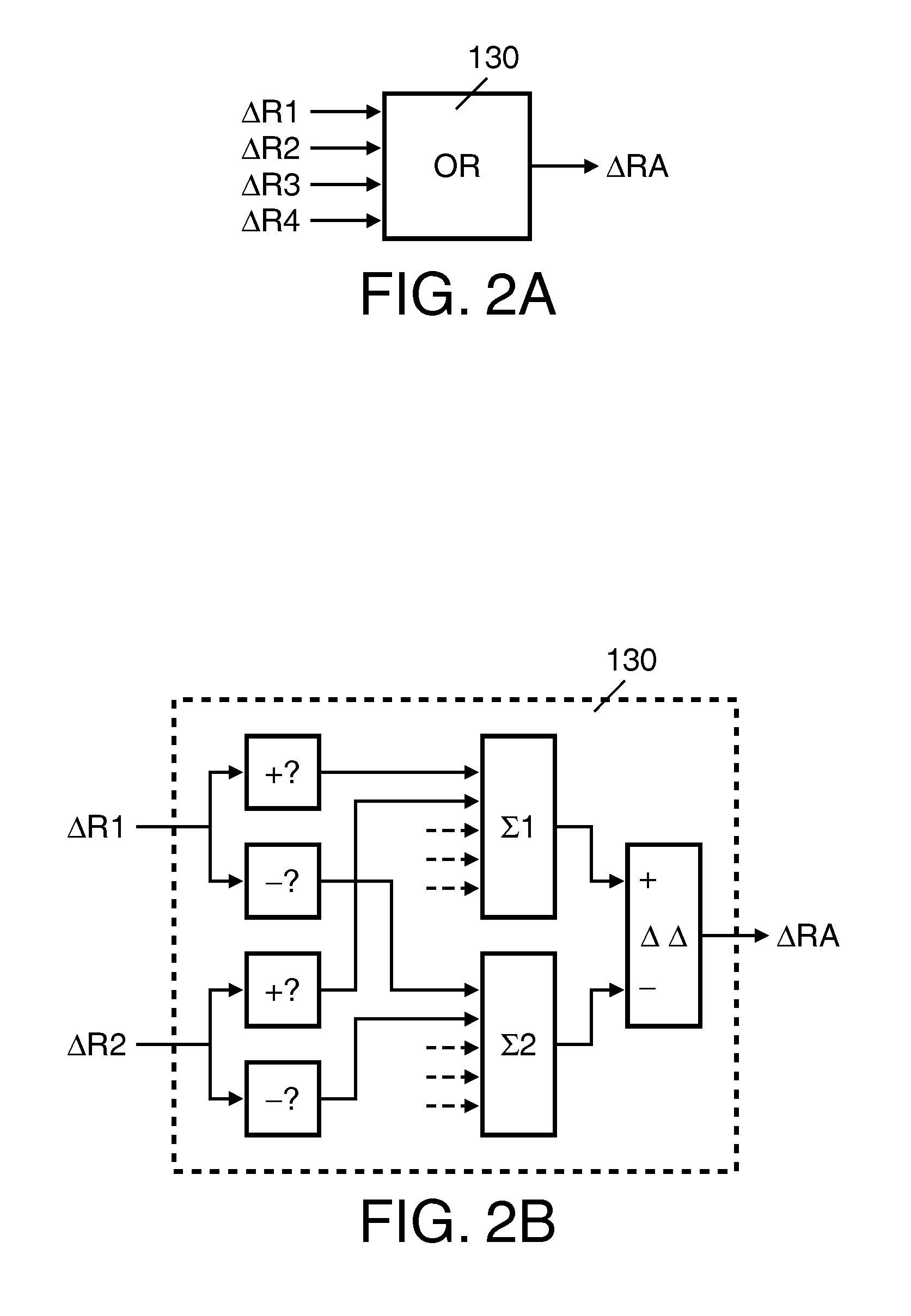
[0044]FIG. 2 shows a data-processing facility according to the invention. Part therein corresponding to those in FIG. 1 have a reference number that is 100 higher. In this embodiment the data-processing facility comprises at least one monitor 151. The monitor 151-154 monitors an available performance of the data-handling facility 120 towards the data-processing device 111-114 to which it is coupled, and compares the available performance with the required performance R1. The monitors 151 calculate a difference ΔR1, ΔR2, ΔR3, ΔR4 between the available and the required performance, which is used to control the activity level of the data-handling facility 120. In the embodiment shown each of the data-processing facilities 111-114 has a respective monitor 151-154. The monitors 151-154 each provide a signal indicative for the difference ΔR1, ΔR2, ΔR3 and ΔR4 between the performance available to and the performance R1-R4 required by their processing device.

[0045]The signal indicative for ...

third embodiment

[0063]It is not necessary that each data-processing device has its own monitor. For example FIG. 6 shows a data-processing facility according to the invention, wherein a plurality of data-processing devices use a single monitor 250 on a time-shared basis. Parts therein corresponding to those in FIG. 1 have a reference number that is 200 higher. In the embodiment shown the shared facility is a memory 222, coupled to each of the processing devices 211-214 by a bus 221. In this embodiment the monitor 250 tracks parameters of transactions for a particular device selected by the general purpose processor 230 and specified by its ID in the bandwidth control register BCR and / or a latency control register WLCR, LRCR. In the AXI transaction protocol transactions comprise such a device identification. Alternatively other transaction protocols may be used that comprise such an identification of the devices involved in the transactions.

[0064]The general purpose processor 230 specifies for which...


PUM


Abstract

A data-processing system is described comprising: • A plurality of data-processing devices (11, 12, 13, 14) • A data-handling facility (20) shared by the data-processing devices, • An aggregation facility (30) for receiving signals (R1, R2, R3, R4) indicative for individual requirements from the data-processing devices for a performance of the shared data-handling facility and for providing a control signal (RA) indicative for a required activity level to meet the aggregated requirements, • a control device (40) for controlling an activity level of the data-handling facility depending on the control signal (RA). Additionally a data-processing method is described.

Description

FIELD OF THE INVENTION[0001]The present invention relates to a data-processing system.[0002]The present invention further relates to a data-processing method.BACKGROUND OF THE INVENTION[0003]Dynamic voltage and / or frequency scaling has been widely proposed to adapt the power consumption of processors to the minimum required level necessary to achieve a required performance. This is in particular important in mobile devices, such as in mobile phones, laptops and pda's, operating on battery power. The performance delivered by such mobile devices not only depends on the performance of the processors used therein, e.g. digital signal processors, general purpose processors etc, but also on the performance of data-handling facilities used by such processors, such as memories and communication networks. Important performance parameters for such data-handling facilities are a bandwidth, i.e. a number of data-units handled per time-unit and a latency, the delay between the request for a hand...

Claims


Application Information

Patent Timeline
Patent Type & Authority Patents(United States)
IPC IPC(8): G06F3/00
CPCG06F1/3203G06F1/324G06F1/3253Y02B60/1217Y02B60/1235Y02D10/00
Inventor KLAPPROTH, PETEREHMANN, GREGPFEIFFER, CLAUS
Owner NXP BV
Why Eureka
Eureka Blog
Learn More