
Pearlite rail

a technology of pearlite and spherical steel, which is applied in the field of pearlite rail, can solve the problems of significant wear on the head top or the head corner portion of the rail, reduce the service life, and increase the amount of wear, so as to maintain the hardness (strength) of the pearlite structure, reduce the stress range of fatigue limit, and improve the effect of fatigue damage resistan

Active Publication Date: 2013-01-29
NIPPON STEEL CORP
View PDF13 Cites 5 Cited by
  • Summary
  • Abstract
  • Description
  • Claims
  • Application Information

AI Technical Summary

Benefits of technology

[0026]In the pearlite rail described in the above (1), since an amount of 0.65 to 1.20% of C, an amount of 0.05 to 2.00% of Si, and an amount of 0.05 to 2.00% of Mn is contained, it is possible to maintain the hardness (strength) of the pearlite structure is maintained and improve a fatigue damage resistance. In addition, a martensite structure which is harmful to fatigue properties is not easily generated, and a reduction in the fatigue limit stress range can be suppressed, so that it becomes possible to enhance fatigue strength.
[0027]In addition, in the pearlite rail, at least part of the head portion and at least part of the bottom portion have a pearlite structure, and the surface hardness of at least part of the head portion and at least part of the bottom portion is in a range of Hv320 to Hv500 and has a maximum surface roughness of less than or equal to 180 μm. Therefore, it becomes possible to enhance the fatigue damage resistance of the rail for the freight railways overseas and the domestic passenger rails.
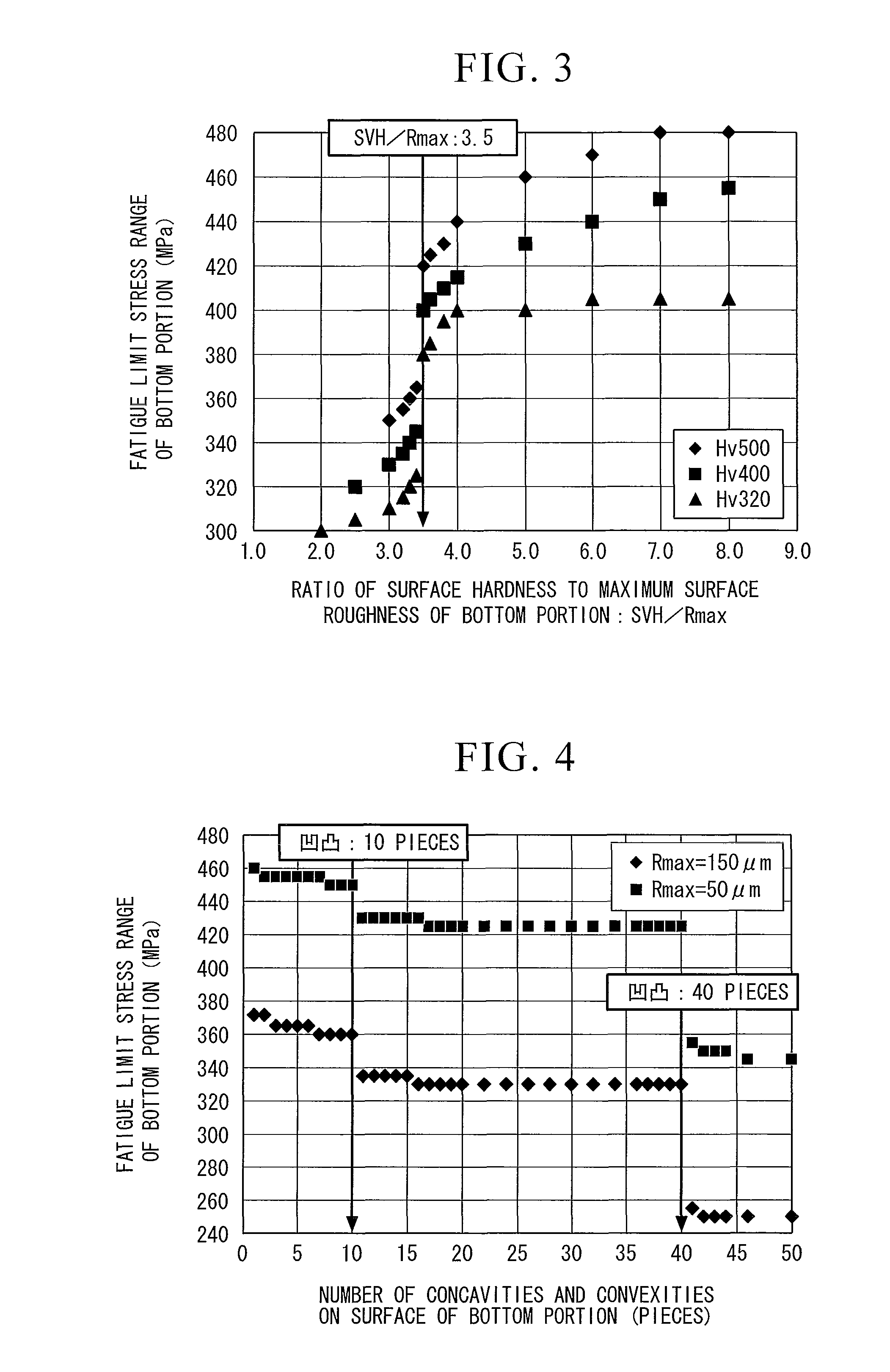
[0028]In the pearlite rail described in the above (2), since the ratio of the surface hardness to the maximum surface roughness is greater than or equal to 3.5, the fatigue limit stress range is increased, so that it becomes possible to enhance the fatigue strength. Therefore, it becomes possible to further improve the fatigue damage resistance of the pearlite rail.
[0029]In the pearlite rail described in the above (3), since the number of concavities and convexities is less than or equal to 40, the fatigue limit stress range is increased, so that the fatigue strength is significantly enhanced.
[0030]In the pearlite rail described in the above (4), since one or two kinds of 0.01 to 2.00% of Cr and 0.01 to 0.50% of Mo are contained, lamellar spacing of the pearlite structure is made finely, so that the hardness (strength) of the pearlite structure is improved and generation of the martensite structure which is harmful to the fatigue properties is suppressed. As a result, it becomes possible to improve the fatigue damage resistance of the pearlite rail.
[0031]In the pearlite rail described in the above (5), since one or two kinds of 0.005 to 0.50% of V and 0.002 to 0.050% of Nb is contained, austenite grains are made finely, so that toughness of the pearlite structure is improved. In addition, since V and Nb prevent a heat-affected zone of the welding joint from softening, it becomes possible to improve the toughness of the pearlite structure and strength of welded joints.

Problems solved by technology

In particular, in rails used for a section through which a large number of trains passes or for sharp curves, significant wear occurs on a head top portion or a head corner portion of the rail (the periphery of corner of the rail head which intensely contacts with flange portions of wheels).
Therefore, there is a problem of a reduction in the service life due to an increase in the amount of wear.
In addition, similarly, in a domestic passenger rails, particularly, in the rail used for sharp curves, the wear progresses remarkably as in the freight railways overseas, so that there is a problem in that the service life is reduced due to an increase in the amount of wear.
In the rail described in Patent Document 1, it becomes difficult to ensure the wear resistance of the head portion of the rail, so that there is a problem in that the service life of the rail is greatly reduced.
However, in recent years, an excessive increase in the density of railway transportation has been progressed, so that the generation of fatigue damage from the head portion or the bottom portion of the rail exists.
As a result, although the rail described in Patent Document 2 is used, there is a problem in that the service life of the rail is not sufficient.

Method used


Image

  • Pearlite rail
  • Pearlite rail
  • Pearlite rail

Examples


examples

[0198]Next, Examples of the invention will be explained.

[0199]Tables 1-1 to 1-4 show chemical components and characteristics of the steel rail (pearlite-based rail) of Examples. Tables 1-1 (steel rails A1 to A19), 1-2 (steel rails A20 to A38), 1-3 (steel rails A39 to A52), and 1-4 (steel rails A53 to A65) show chemical component values, microstructures of the surfaces of the head portion and the bottom portion of the rail, surface hardness (SVH), the maximum surface roughness (Rmax), value of surface hardness (SVH) / the maximum surface roughness (Rmax), and the number of concavities and convexities (NCC) that exceed 0.30 times the maximum surface roughness, fatigue limit stress range (FLSR). Moreover, results of fatigue tests performed by methods shown in FIGS. 6A and 6B are included.

[0200]Tables 2-1 (steel rails a1 to a10) and 2-2 (steel rails a11 to a20) show chemical components and characteristics of steel rails compared to the steel rails (A1 to A65) of Examples. Tables 2-1 and 2...


PUM

PropertyMeasurementUnit
surface roughnessaaaaaaaaaa
lengthaaaaaaaaaa
frequencyaaaaaaaaaa

Abstract

A pearlite rail contains, by mass %, 0.65 to 1.20% of C; 0.05 to 2.00% of Si; 0.05 to 2.00% of Mn; and the balance composed of Fe and inevitable impurities, wherein at least part of the head portion and at least part of the bottom portion has a pearlite structure, and the surface hardness of a portion of the pearlite structure is in a range of Hv320 to Hv500 and a maximum surface roughness of a portion of the pearlite structure is less than or equal to 180 μm.

Description

TECHNICAL FIELD[0001]The present invention relates to a pearlite rail which enhances fatigue damage resistance of the head portion and the bottom portion of the rail. In particular, the present invention relates to a pearlite rail which is used for sharp curves in domestic and freight railways overseas.[0002]Priority is claimed based on Japanese Patent Application No. 2009-189508, filed on Aug. 18, 2009, the contents of which are incorporated herein by reference.BACKGROUND ART[0003]With regard to freight railways overseas, in order to achieve high efficiency in railway transportation, a carrying capacity of freight loads has been improved. In particular, in rails used for a section through which a large number of trains passes or for sharp curves, significant wear occurs on a head top portion or a head corner portion of the rail (the periphery of corner of the rail head which intensely contacts with flange portions of wheels). Therefore, there is a problem of a reduction in the serv...

Claims


Application Information

Patent Timeline
Patent Type & Authority Patents(United States)
IPC IPC(8): C22C38/02C22C38/04
CPCC21D9/04C22C38/04C22C38/02C21D2211/004C21D2211/009C21D2221/02C21D2221/00C22C38/001C22C38/002C22C38/20
Inventor UEDA, MASAHARUSONOYAMA, KYOHEITANAHASHI, TAKUYAMIYAZAKI, TERUHISAIWANO, KATSUYA
Owner NIPPON STEEL CORP
Learn More