Environmentally stable sensors and methods of using the same
a biosensor and environmental stability technology, applied in the field of environmental stability biosensor construction, can solve the problems of limiting the number of useful compounds, the difficulty of culturing extremophiles, and the destabilization of ligand binding proteins, so as to achieve a robust platform for nanosensor construction and engineering, the effect of enhancing the degree of mutagenesis and enhancing the enthalpic and entropic contributions
- Summary
- Abstract
- Description
- Claims
- Application Information
AI Technical Summary
Benefits of technology
Problems solved by technology
Method used
Image
Examples
example 1
Sensor Construction
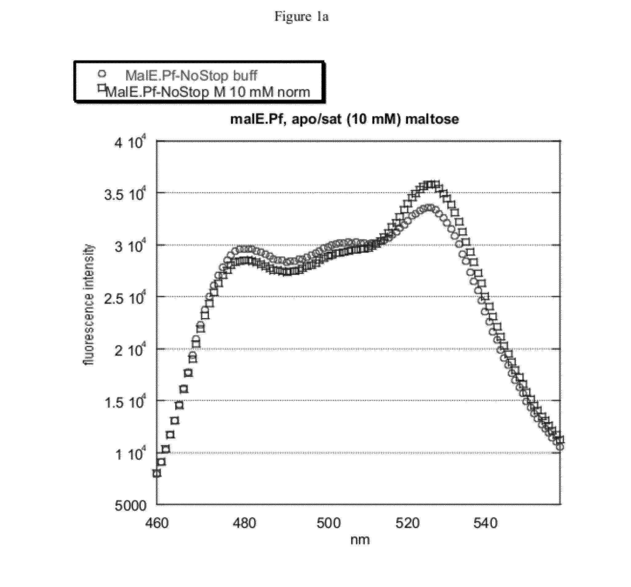
[0057]Initially, the thermophilic-derived nanosensor construct was obtained from Pyrococcus furiosus, e.g., the maltose-binding protein (malE) sensor (malE_Pf). Several more thermophilic-derived sensors have been constructed (malE from Thermococcus litoralis, malE from Thermus thermophilus (malE_Tt), mglB from Thermus thermophilus, q72hc2 (a branched amino-acid binding protein) from Thermus thermophilus, 2609 (an amino-acid binding protein) from Thermus thermophilus, 1033 (a glutamate-binding protein) from Thermus thermophilus, and malE from Alicyclobacillus acidocaldarius (malE_Aa)).
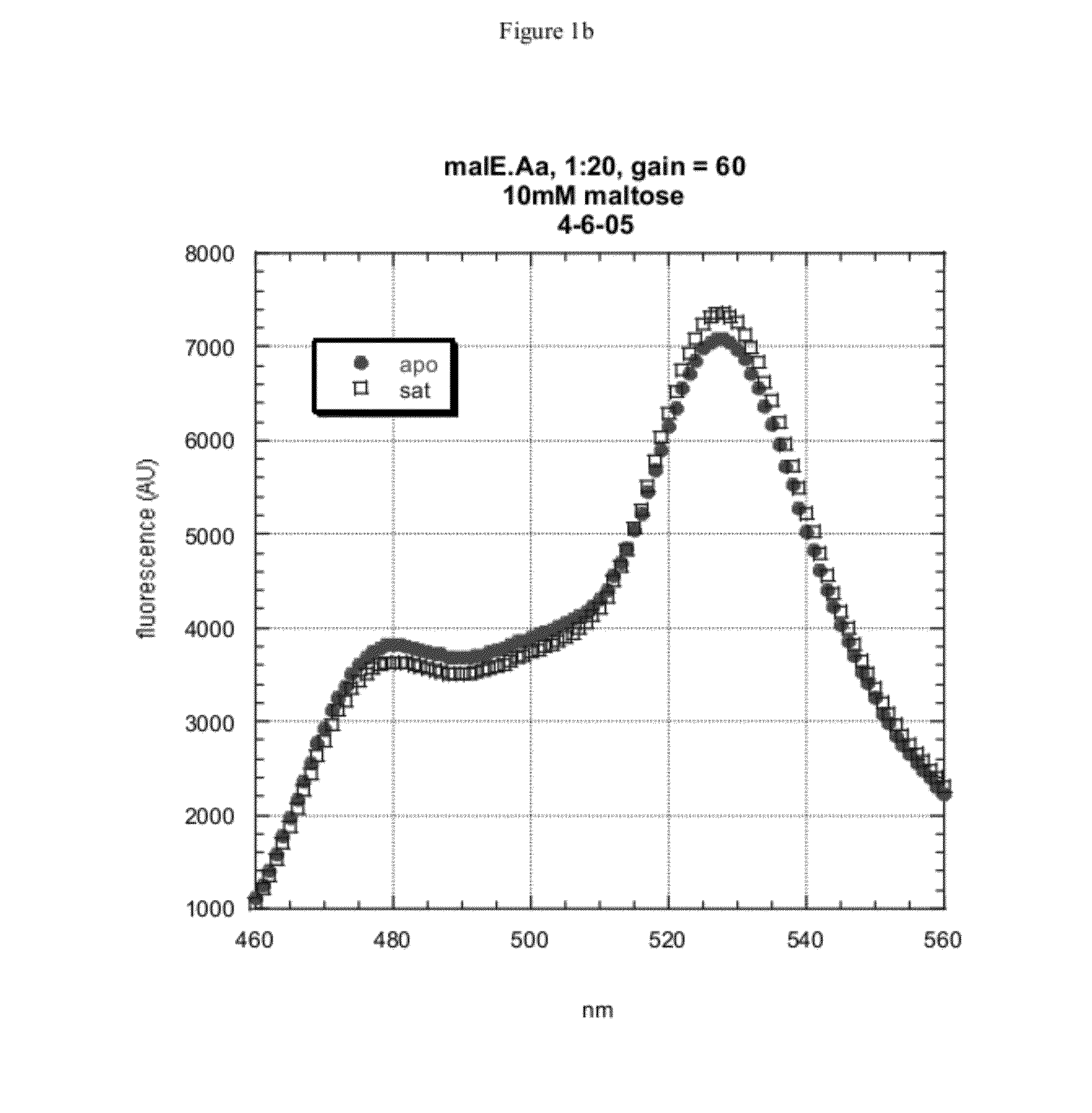
[0058]The maltose-binding protein (malE) from Alicyclobacillus acidocaldarius was chosen as a high-priority target for nanosensor construction because of its known thermal stability and acid resistance. The malE gene was isolated from genomic DNA by PCR and moved into the FLIP format using the recently-developed GATEWAY_FLIP cloning strategy. The same method applies to the constructio...
example 2
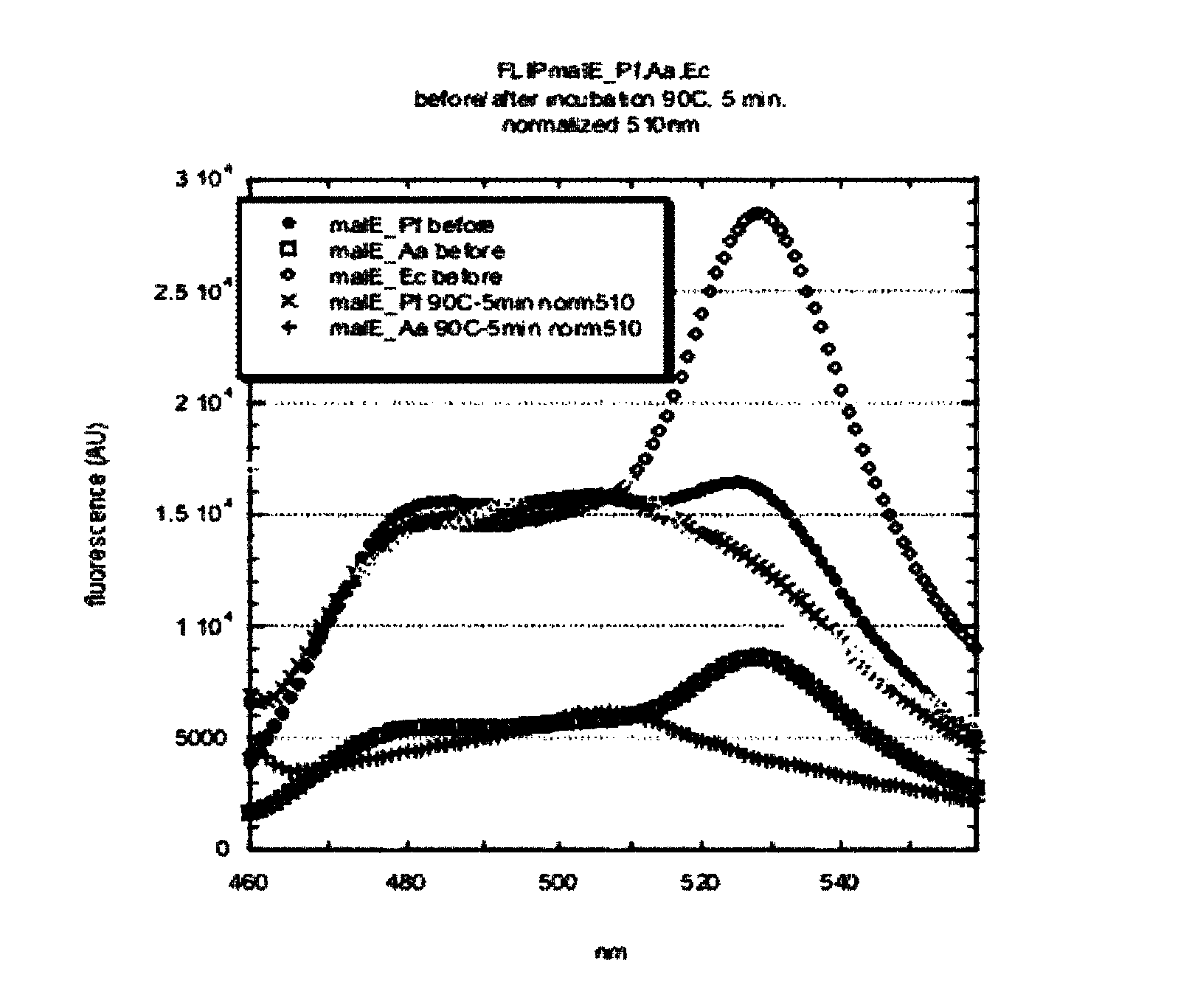
[0062]The three nanosensors were exposed to elevated temperatures (from 60° C. to 95° C.) for five minutes, then brought back down to room temperature and promptly analyzed in the fluorimeter. All sensors showed no adverse effects from exposure to 60° C. The mal_Aa protein showed some sensitivity to exposure to 70° C., and was destabilized by 85° C. The malE_Ec nanosensor showed slightly less sensitivity to 70° C., but was destabilized soon thereafter. The malE_Pf sensor showed no sensitivity to temperatures up to 80° C., and it is likely that the FPs unfold at ˜85° C., leading to the collapse of the signal of all three sensors in this region (FIG. 3). The increase of the fluorescence signal upon partial destabilization has been seen before, and is likely due to formation of a molten globule state.
example 3
Chemical Denaturant Resistance
[0063]The three sensors were also exposed to increasing concentrations of the chemical denaturant GuHCl (guanidinium hydrochloride), and fluorescence spectra were recorded. Again, the extreme conditions affect both the BP and FP portions of the nanosensors, and as well the high chloride concentration in the GuHCl solutions leads to some quenching of the FPs, particularly the YFP. In spite of this, it is possible to observe trends between the different sensors. The malE_Pf sensor is by far the most resistant to GuHCl denaturation, at neutral pH. After this, the malE_Ec and then lastly the malE_Aa sensor follow. Upon exposure to low pH (4.1), the malE_Pf sensor is still the most stable, but has been destabilized. The malE_Aa sensor follows this, somewhat destabilized versus neutral pH. The malE_Ec has been significantly destabilized by exposure to very acid pH (FIG. 4).
PUM
| Property | Measurement | Unit |
|---|---|---|
| boiling point | aaaaa | aaaaa |
| temperatures | aaaaa | aaaaa |
| temperatures | aaaaa | aaaaa |
Abstract
Description
Claims
Application Information
 - R&D
- Intellectual Property
- Life Sciences
- Materials
- Tech Scout
- Unparalleled Data Quality
- Higher Quality Content
- 60% Fewer Hallucinations
Browse by: Latest US Patents, China's latest patents, Technical Efficacy Thesaurus, Application Domain, Technology Topic, Popular Technical Reports.
© 2025 PatSnap. All rights reserved.Legal|Privacy policy|Modern Slavery Act Transparency Statement|Sitemap|About US| Contact US: help@patsnap.com


