Sheet feeding device and image forming apparatus
a feeding device and a technology for forming apparatus, applied in the direction of transportation and packaging, thin material processing, article separation, etc., can solve the problems of retard rollers with significantly short durability life spans, paper jams, retard rollers with co-rotation failures, etc., to prolong the durability life span of retard rollers and simple structure with ease
- Summary
- Abstract
- Description
- Claims
- Application Information
AI Technical Summary
Benefits of technology
Problems solved by technology
Method used
Image
Examples
first embodiment
[0030]Next, the separation portions 26, 27, and 28 mounted in the sheet feeding portion 2 will be described in greater detail with reference to FIGS. 2A and 2B as well as FIG. 1.
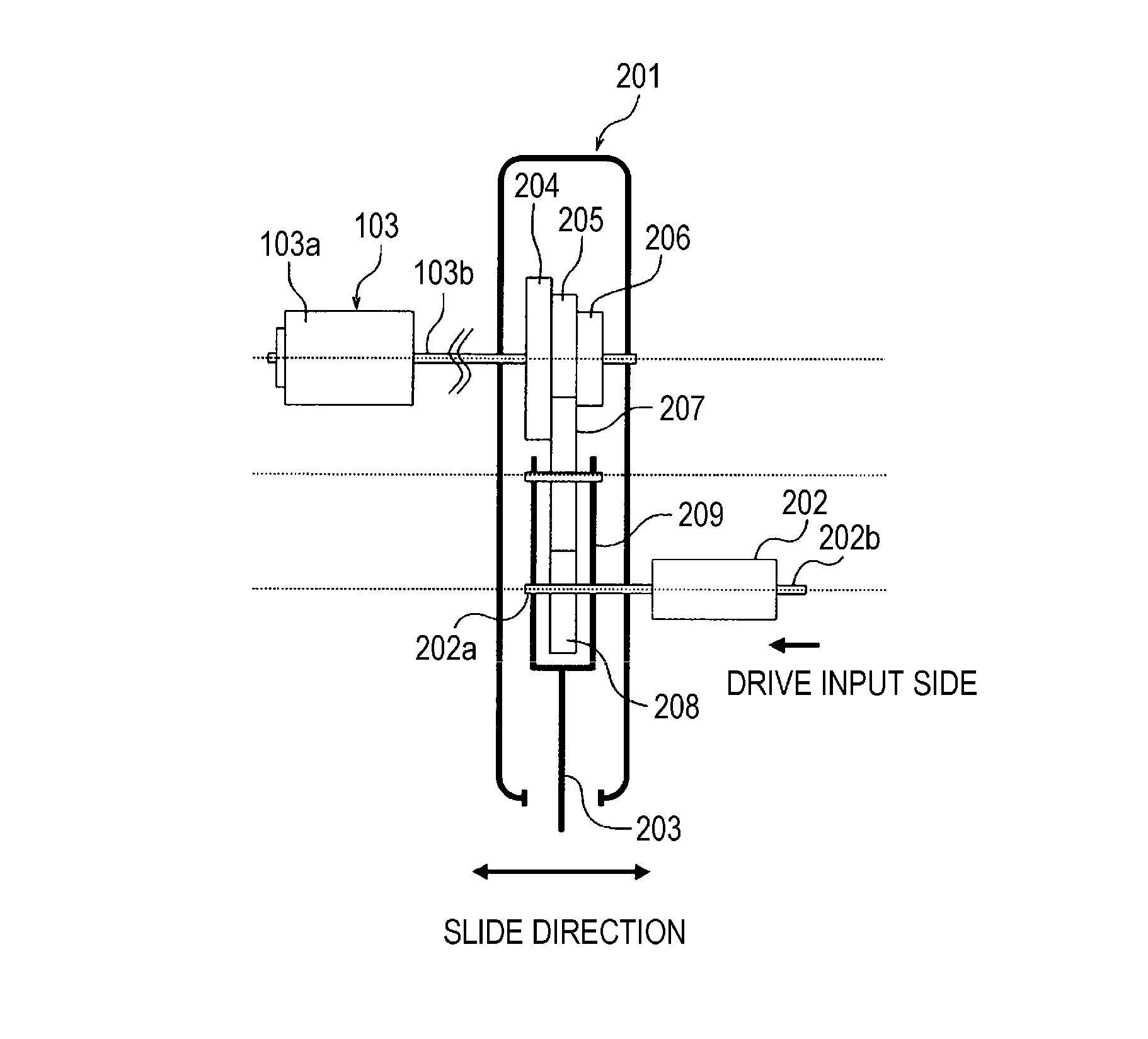
[0031]FIG. 2A is a plan view illustrating the retard roller 103, a torque limiter 202, and a speed changing device 201 according to the first embodiment. FIG. 2B is a side view illustrating the structure of FIG. 2A.
[0032]The separation portions 26, 27, and 28 according to the first embodiment are configured to be able to completely change a rotary torque, which is transmitted to the retard roller 103 through the torque limiter 202 from a drive source (not illustrated), through an operation of the operation handle by an operator such as a service person. Since the separation portions 26, 27, and 28 have the same structure, a description will be made only about the separation portion 27 disposed on the downstream side, in the sheet feed direction, of the pick-up roller 24 which sends the sheet S of the univer...
second embodiment
[0059]As illustrated in FIG. 1, the image forming apparatus 1A includes the sheet feeding portion 2A which feeds a sheet S, an image forming portion 3 which forms an image on the sheet S, a fixing portion 4 which fixes the image formed on the sheet S, and a discharging portion 5 which discharges the sheet S to which the image is fixed.
[0060]The sheet feeding portion 2A includes: a sheet deck 20; a plurality of universal cassettes 21 and 22; pick-up rollers 23, 24, and 25; separation portions 26A, 27A, and 28A; a pair of pulling-out rollers (not illustrated); and a pair of registration rollers (not illustrated). The separation portions 26A, 27A, and 28A are disposed on the downstream side of the pick-up rollers 23, 24, and 25 in the sheet feed direction to separate the sheets S fed by the pick-up rollers 23, 24, and 25 one by one.
[0061]Next, the separation portions 26A, 27A, 28A provided in the sheet feeding portion 2A according to the second embodiment will be described in detail. ...
PUM
 Abstract
Description
Claims
Application Information
 - R&D
- Intellectual Property
- Life Sciences
- Materials
- Tech Scout
- Unparalleled Data Quality
- Higher Quality Content
- 60% Fewer Hallucinations
Browse by: Latest US Patents, China's latest patents, Technical Efficacy Thesaurus, Application Domain, Technology Topic, Popular Technical Reports.
© 2025 PatSnap. All rights reserved.Legal|Privacy policy|Modern Slavery Act Transparency Statement|Sitemap|About US| Contact US: help@patsnap.com


