
Reverse umbrella type oxidation ditch aeration machine impeller structure

The technology of aerator and oxidation ditch is applied in the structural field of the impeller of the inverted umbrella type oxidation ditch aerator, which can solve the problems of aggravating the energy crisis and the high operation cost of sewage treatment facilities, and achieves high structural efficiency, mechanical strength and durable life. High, enhance the effect of oxygenation

Inactive Publication Date: 2012-05-16
TSINGHUA UNIV
View PDF0 Cites 0 Cited by
  • Summary
  • Abstract
  • Description
  • Claims
  • Application Information

AI Technical Summary

Problems solved by technology

On the one hand, high power consumption has resulted in high operating costs of sewage treatment facilities; on the other hand, high power consumption has also aggravated my country's current energy crisis

Method used


Image

  • Reverse umbrella type oxidation ditch aeration machine impeller structure
  • Reverse umbrella type oxidation ditch aeration machine impeller structure
  • Reverse umbrella type oxidation ditch aeration machine impeller structure

Examples


Embodiment 1

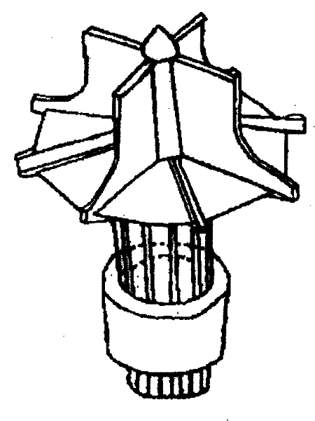
[0027] according to Figure 5 For the size of the aerator shown, the aerator is reduced by 40 times, and the aerator model of the same structure is made ( figure 1 As shown), the three aerators developed by Guozhen were also scaled down in the same scale to make aerator models ( Figure 2-4 shown). The aerator model was used to test the flow state in the oxidation ditch of the small test model, and the results showed that the plug flow and aerator performance of the aerator were better than the other three aerator structures (Table 1).

[0028] Table 1 Small test model flow rate comparison

[0029] Upper level horizontal speed Upper level vertical speed Lower level horizontal speed Lower level vertical speed

[0030]The present invention 0.00032757 -0.020277 -0.0076853 -0.0068225

[0031] in the upstream channel

[0032] Ds380 -0.00028131 -0.023339 -0.0059433 -0.0089323

[0033] close to exposure

[0034] Single layer 0....

Embodiment 2

[0062] The aerator with this structure and the other three aerators of Guozhen are used to simulate the actual oxidation ditch, and the calculation fluid dynamics model is used to simulate the push flow and aeration function of the aerator with the actual size structure. As can be seen from the test results, the performance of the aerator configuration proposed by the invention is better than that of the above three aerator configurations. Under the same rotating speed and input power conditions, the aerator configuration of this configuration The average flow velocity and output power of different sections in the middle of the oxidation ditch are higher than those of the other three types of aerators ( Figure 8 ,Table 2).

[0063] Table 2 Output Power Comparison

[0064] model Ds380 Dss-19Y this invention single layer Power(kW) 84.8 82.9 95.14 78.5 Multiples of single-layer aerator power 1.08 1.056 1.21 1


PUM

PropertyMeasurementUnit
angleaaaaaaaaaa
diameteraaaaaaaaaa

Abstract

The invention belongs to the technical field of sewage treatment plant manufacturing in environmental protection, more particularly relates to the structure of impellers of an inverted umbrella type oxidation ditch aeration machine. The main structure is an inverted cone with a bottom included angle being 140 degree, 8 impellers are embedded on the cone surface of the cone body all together, the blades of the impellers are perpendicular to the cone surface, and the impellers include 4 short-blade impellers and 4 small-blade impellers; and the 4 short-blade impellers and the 4 small-blade impellers are alternately arranged with equal spaces. Part of the blades at the lower part of the short-blade impeller are prolonged directly so as to stir fluids at the bottom, increase the up-and-down cycling speed and the horizontal flowing speed of sewage, and improve three functions of the aeration machine, that is, oxygenizing, stirring and plug-flowing. Compared with the present structure, the structure is more effective and can be applied more widely to the aeration and plug-flowing of a deep oxidation ditch.

Description

technical field [0001] The invention belongs to the technical field of sewage treatment equipment manufacturing in environmental protection. In particular, it relates to the structure of an impeller of an inverted umbrella type oxidation ditch aerator. Specifically, this technology is mainly used in the technological transformation of the oxidation ditch process using surface aeration, the upgrading of aeration equipment and the optimization design of the process. The new aerator can meet the equipment requirements of the new oxidation ditch process and enhance the effect of aeration and push flow. Improve the treatment efficiency of the oxidation ditch, and at the same time reduce the operating energy consumption of the oxidation ditch aeration equipment. Background technique [0002] The urban sewage treatment is one of the energy-intensive industries. In the operating cost (including depreciation fees, etc.) of a conventional urban sewage treatment plant, electricity cos...

Claims


Application Information

Patent Timeline
Patent Type & Authority Patents(China)
IPC IPC(8): A01K61/00C02F3/12
CPCY02A40/81Y02W10/10
Inventor 施汉昌施慧明刘艳臣
Owner TSINGHUA UNIV
Learn More