
System and method for depth from defocus imaging

a technology of depth from defocus and imaging, applied in the field of contactless multifingerprint collection devices, can solve the problems of generating poor quality fingerprint images, reasonable error estimates, and significant drawbacks of contact-based fingerprint readers

Active Publication Date: 2012-12-25
GENERAL ELECTRIC CO
View PDF13 Cites 25 Cited by
  • Summary
  • Abstract
  • Description
  • Claims
  • Application Information

AI Technical Summary

Benefits of technology

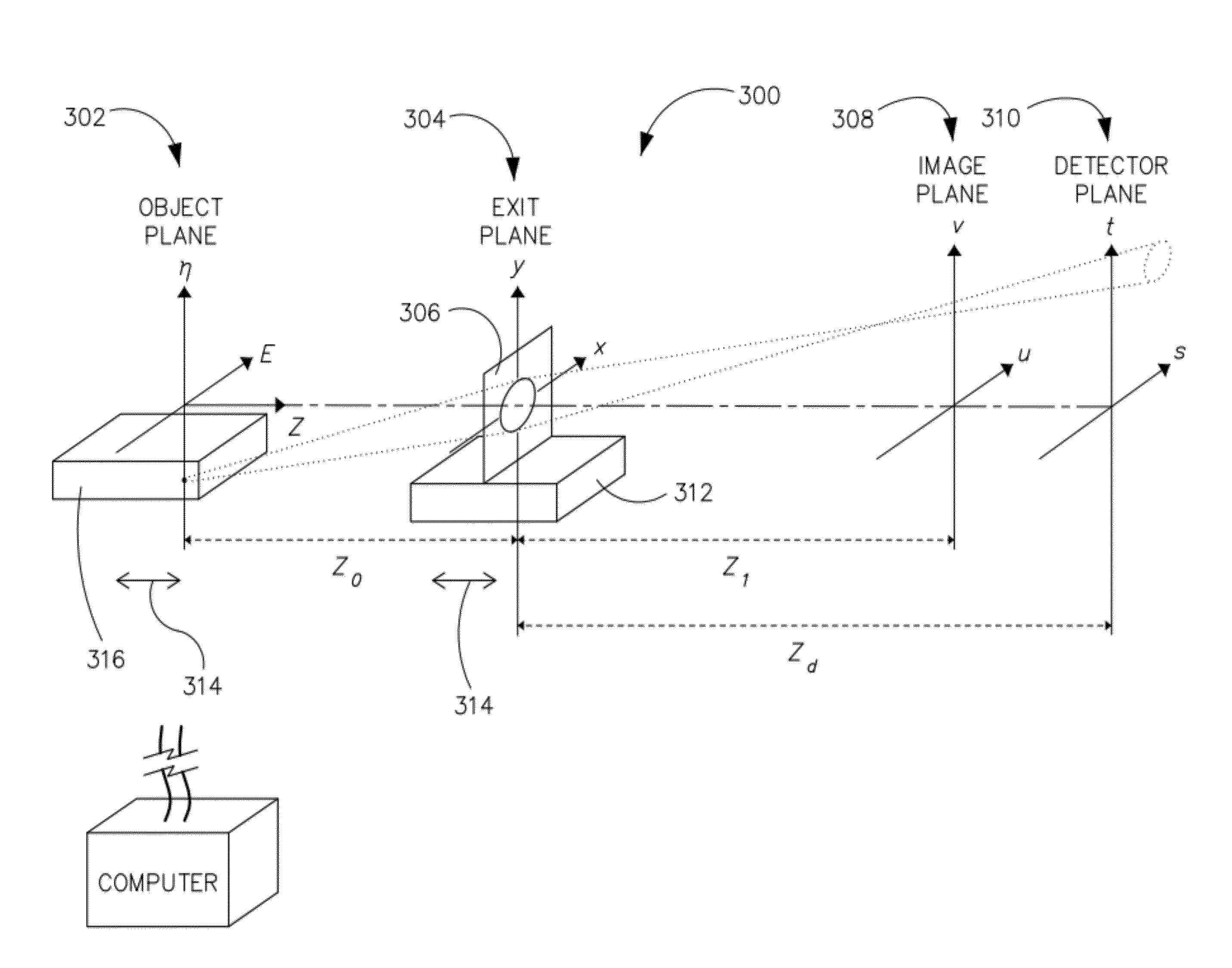
[0012]According to one aspect of the invention, an imaging system includes an imaging system includes a positionable device configured to axially shift an image plane, wherein the image plane is generated from photons emanating from an object and passing through a lens, a detector plane positioned to receive the photons of the object that pass through the lens, and a computer programmed to characterize the lens as a mathematical function, acquire two or more elemental images of the object with the image plane of each elemental image at different axial positions with respect to the detector plane, determine a focused distance of the object from the lens, based on the characterization of the lens and...

Problems solved by technology

However, contact-based fingerprint readers have significant drawbacks associated therewith.
For example, in a field environment, dirt, grease or other debris may build up on the window of contact based fingerprint readers, so as to generate poor quality fingerprint images.
For highly corrected imaging optics and white light illumination, the PSF resembles a Gaussian or a pillbox and assuming so typically generates a depth estimator with a reasonable error.
However, it can be shown that depth estimation based on DFD is highly sensitive to proper determination of PSF structure, and applying DFD based on Gaussian (or pillbox) PSF models to an imaging system where PSF departs from this assumption results in unreliable depth estimates.
That is, the simplified model does not adequately describe physical lens behavior when there is a high degree of aberration, when a lens has a small depth-of-field compared to object size, when quasi-monochromatic light is used (such as an LED), or when monochromatic light is used (such as a laser), as examples.
Thus, known DFD systems fail to estimate object distance and fail to accurately reproduce a fingerprint in a contactless system.

Method used


Image

  • System and method for depth from defocus imaging
  • System and method for depth from defocus imaging
  • System and method for depth from defocus imaging

Examples


Embodiment Construction

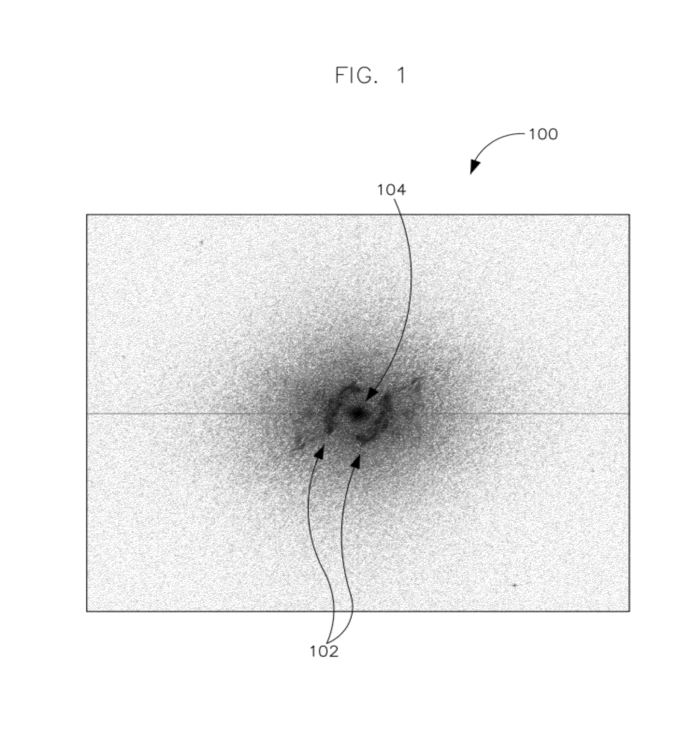
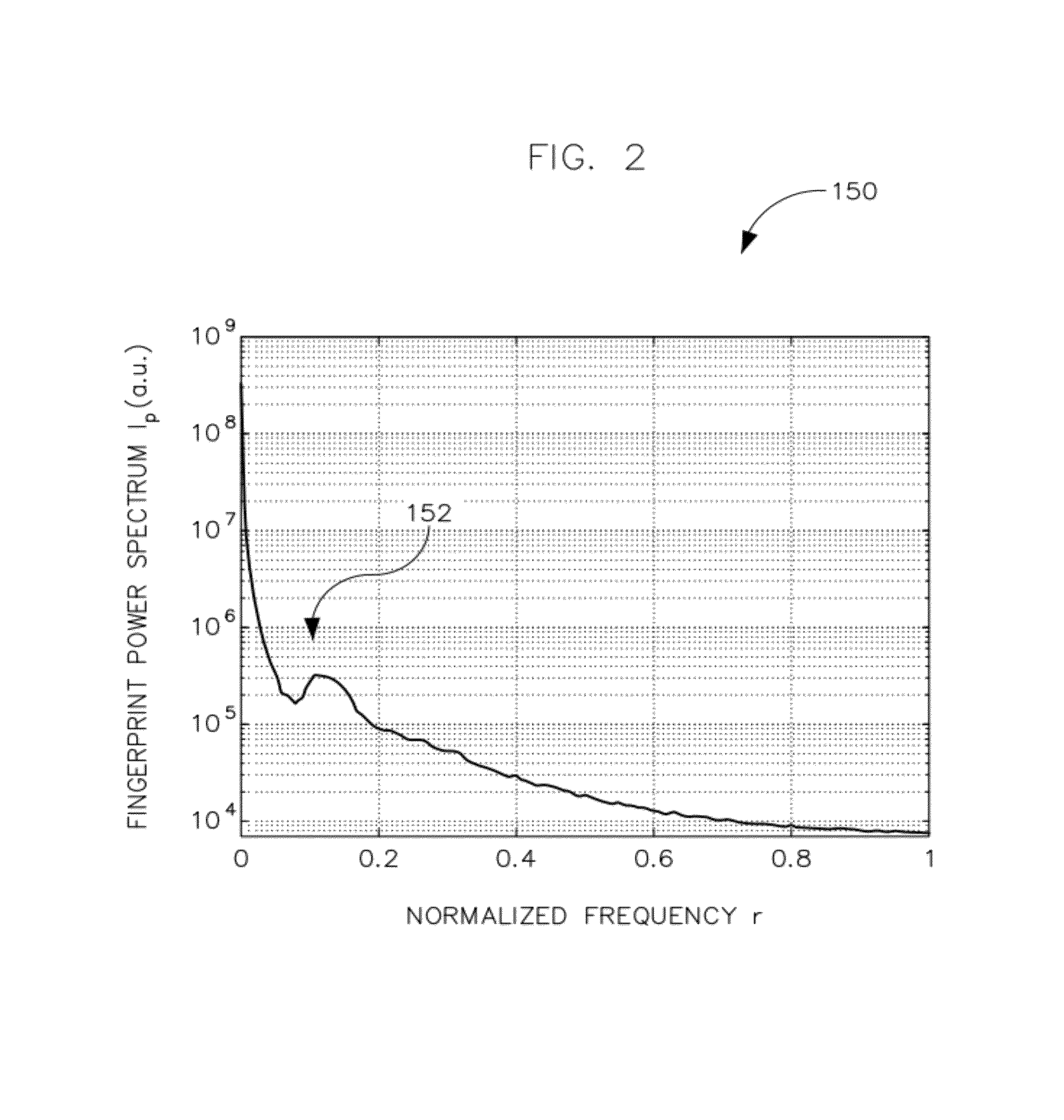
[0024]According to the invention, a mathematical model is used that governs lens behavior. The model is affected by object distance and physical characteristics of the lens (i.e., aberrations, focal length, etc. . . . ). Information from focus planes (DFF) and from an amount of defocus (DFF) is combined to yield a depth map. Following is a description of an algorithm for a contactless fingerprint imaging system according to embodiments of the invention. However, the invention is not limited to such a system and it is contemplated that the disclosed invention may be applicable to any imaging system that uses passive depth estimation from a set of slightly defocused images such as 3D microscopic profilometry for inspection in industrial applications, 3D borescope imaging, 3D in-situ medical imaging, 3D consumer cameras (with proper focus shifting lenses), passive imaging for 3D target recognition (defense or security industries), and the like.

[0025]FIG. 1 illustrates a typical fingerp...


PUM


Abstract

An imaging system includes a positionable device configured to axially shift an image plane, wherein the image plane is generated from photons emanating from an object and passing through a lens, a detector plane positioned to receive the photons of the object that pass through the lens, and a computer programmed to characterize the lens as a mathematical function, acquire two or more elemental images of the object with the image plane of each elemental image at different axial positions with respect to the detector plane, determine a focused distance of the object from the lens, based on the characterization of the lens and based on the two or more elemental images acquired, and generate a depth map of the object based on the determined distance.

Description

GOVERNMENT LICENSE RIGHTS[0001]This invention was made with Government support under grant number HSHQDC-10-C-00083 awarded by the Department of Homeland Security. The Government has certain rights in the invention.BACKGROUND OF THE INVENTION[0002]Embodiments of the invention relate generally to a system and method for depth from defocus imaging, and more particularly to a contactless multi-fingerprint collection device.[0003]It is well known that the patterns and geometry of fingerprints are different for each individual and are unchanged over time. Thus fingerprints serve as extremely accurate identifiers of an individual since they rely on un-modifiable physical attributes. The classification of fingerprints is usually based on certain characteristics such as arch, loop or whorl, with the most distinctive characteristics being the minutiae, the forks, or endings found in the ridges and the overall shape of the ridge flow.[0004]Traditionally, fingerprints have been obtained by mea...

Claims


Application Information

Patent Timeline
IPC IPC(8): G06K9/40H04N9/04
CPCH04N5/23219G06T7/0069G06K9/00033G06K2209/40G06T7/571G02B27/0075G06V40/1312G06V2201/12G06V10/10G06V10/40H04N23/611
Inventor DANESHPANAH, MOHAMMAD MEHDIHARDING, KEVIN GEORGEABRAMOVICH, GILGRAY, DANIEL CURTIS
Owner GENERAL ELECTRIC CO
Learn More