Eureka AIR delivers breakthrough ideas for toughest innovation challenges, trusted by R&D personnel around the world.

Vapor deposition reactor

a vapor deposition reactor and vapor deposition technology, which is applied in the direction of chemical vapor deposition coating, metal material coating process, coating, etc., can solve the problems of reducing the efficiency of the ald reactor, the time required for purging/pumping process is long, and the design of the prior art ald reactor is rather difficult to apply remote plasma, so as to improve the deposition efficiency of precursors and reduce the time required for purging/pumping process

Inactive Publication Date: 2012-12-18
VEECO ALD
View PDF83 Cites 214 Cited by
  • Summary
  • Abstract
  • Description
  • Claims
  • Application Information

AI Technical Summary

Benefits of technology

[0010]It is, therefore, an object of the present invention to provide a vapor deposition reactor that exhibits homogeneous film properties yet has an improved deposition efficiency of precursors and a substantially reduced time required for a purge / pumping process.
[0011]It is also another object of the present invention to provide a vapor deposition reactor which does not require a fast-switching high speed ALD valve.
[0012]It is yet another object of the present invention to provide a vapor deposition reactor designed to make it easier for users to apply remote plasma, use super high frequencies including microwave and irradiate ultraviolet rays.

Problems solved by technology

In particular, when large area substrates are used this phenomenon becomes more evident and it may even cause a serious problem, for example, compositions may vary or film properties may be changed according to the locations of an injection port and an exhaust port.
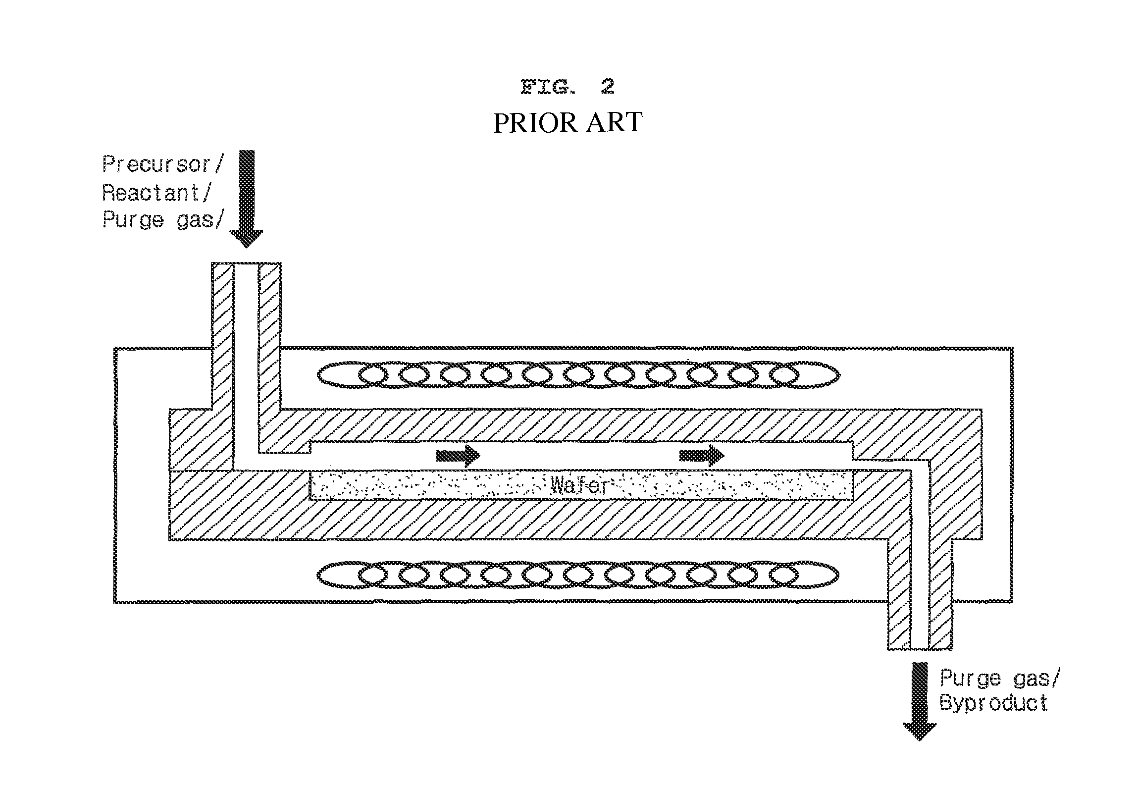
Meanwhile, a reactor using such a shower-head injection port has a large volume so that it takes long to carry out a purge / pumping process and uses a large amount of precursors and reactants.
This actually causes problems related to the lifespan of a valve.
Moreover, both ALD reactors of the prior art are designed to be rather difficult for the application of remote plasma, the use of high frequencies including microwave, UV irradiation and so on.

Method used


Image

  • Vapor deposition reactor
  • Vapor deposition reactor
  • Vapor deposition reactor

Examples


Embodiment Construction

[0033]Hereinafter, preferred embodiments of the present invention will be set forth in detail with reference to the accompanying drawings so that those skilled in the art can easily carry out the invention.

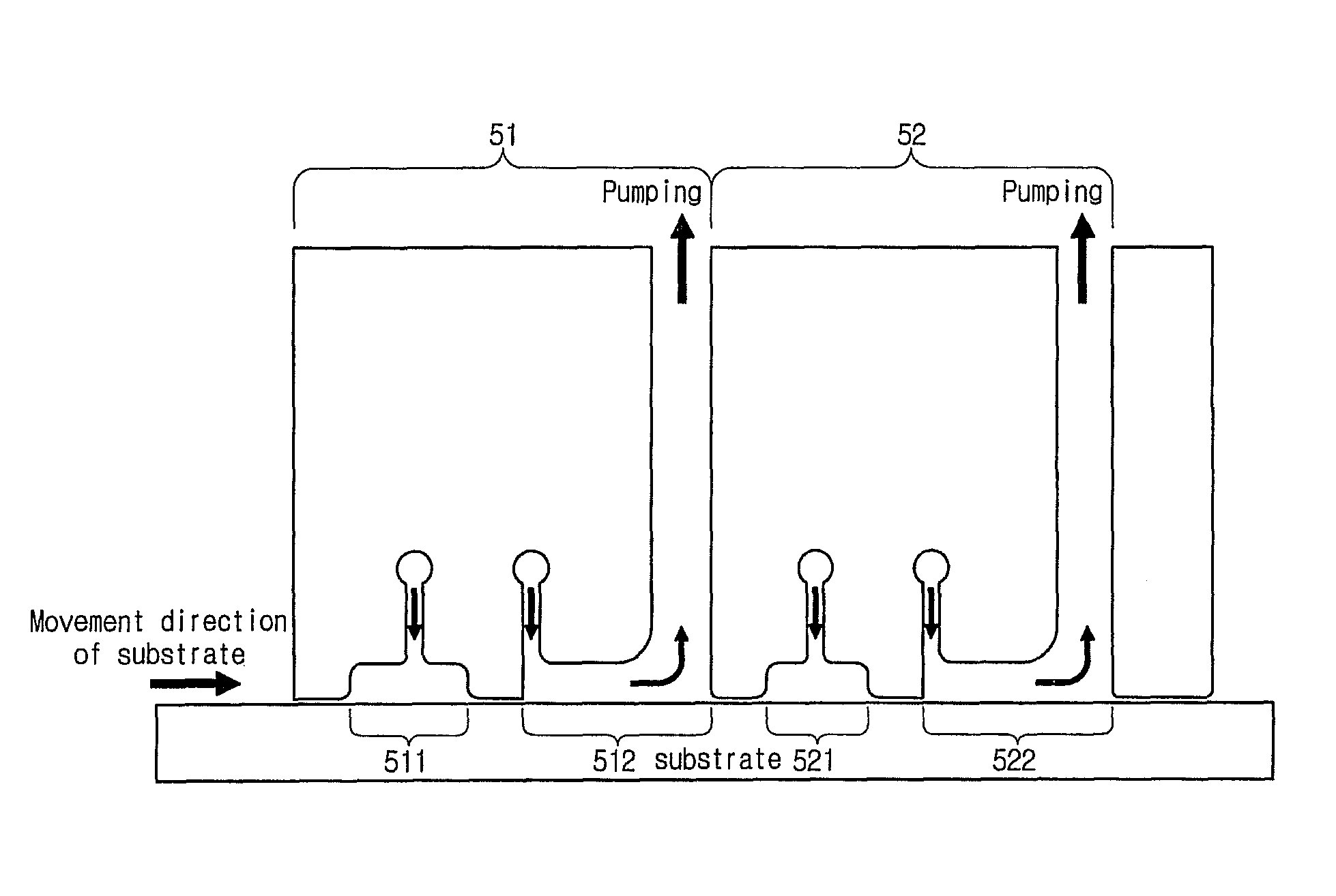
[0034]A vapor deposition reactor according to an embodiment of the invention has a configuration where a substrate or a vapor deposition reactor moves in non-contact state with each other to allow the substrate to pass by the reactor. A portion of the reactor being open to the substrate is a place where a precursor, a purge gas, or a reactant outflows from the reactor. The following will describe a reactor with the configuration aforementioned, by relating to a exemplary situation where a precursor, a purge gas, or a reactant outflows downward from the reactor, and the substrate travels along a lower part of the reactor.

[0035]As shown in FIG. 4, a basic module of a vapor deposition reactor according to an embodiment of the invention is provided with an injection unit 41 and an exh...


PUM

PropertyMeasurementUnit
diameteraaaaaaaaaa
sizeaaaaaaaaaa
widths L1-L5aaaaaaaaaa

Abstract

A vapor deposition reactor has a configuration where a substrate or a vapor deposition reactor moves in a non-contact state with each other to allow the substrate to pass by the reactor and an injection unit and an exhaust unit are installed as a basic module of the reactor for receiving a precursor or a reactant and for receiving and pumping a purge gas, respectively. With the use of a small-size inlet for the reactor, homogeneous film properties are obtained, the deposition efficiency of precursors is improved, and an amount of time required for a purge / pumping process can be reduced. In addition, since the reactor itself is configured to reflect each step of ALD, it does not need a valve. Moreover, the reactor makes it easier for users to apply remote plasma, use super high frequencies including microwave, and UV irradiation.

Description

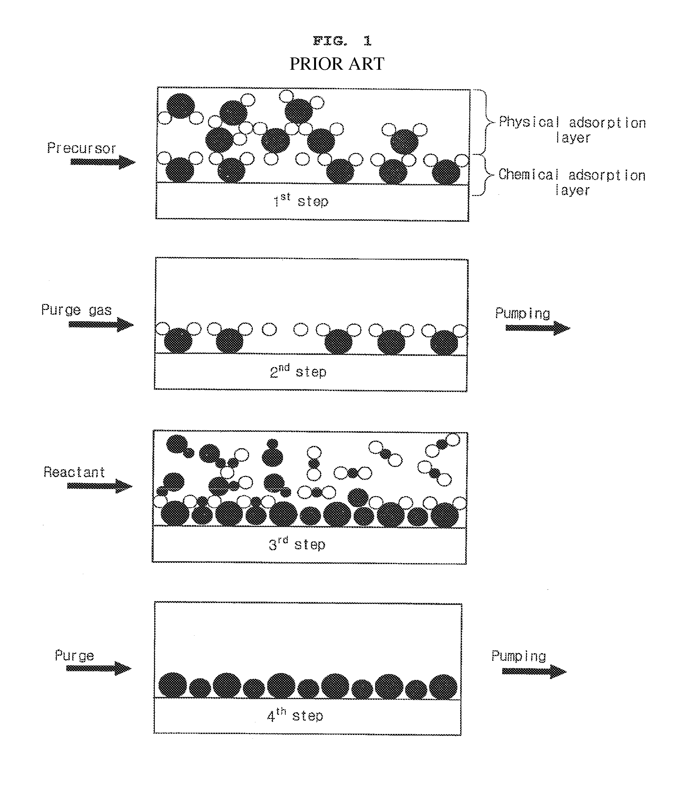
BACKGROUND OF THE INVENTION[0001]1. Field of the Invention[0002]The present invention relates to a reactor used for a vapor deposition scheme.[0003]Recently, a technique of atomic layer deposition (hereinafter referred to as ‘ALD’) has been widely used as a vapor deposition method. For better understanding of the principle(s) of the present invention the following will explain about an ALD reactor as an exemplary prior art, but it should be noted that the present invention is not limited thereto.[0004]2. Description of the Related Art[0005]ALD injects, as shown in FIG. 1, one or more precursors into a reactor and carries out a purge / pump of the precursor to maintain or leave one or more molecule layers on a substrate. Then it injects one or more reactants into the reactor and carries out a purge / pump to obtain one or more mono-atomic reacted layers. Therefore, one or more mono-atomic layers are formed through one cycle consisting of four steps.[0006]A conventional ALD reactor adopts...

Claims


Application Information

Patent Timeline
Patent Type & Authority Patents(United States)
IPC IPC(8): C23C16/00C23C16/455C23C16/46C23C16/54C23C16/511
CPCC23C16/45551
Inventor OH, JAE-EUNG
Owner VEECO ALD
Why Eureka
Eureka Blog
Learn More