
Aspirators with bodies comprising wound filaments

a technology of wound filaments and aspirators, which is applied in the field of aspirators, can solve the problems of material being susceptible to degradation, and the possibility of disadvantage in drilling gas-entry apertures through the walls of the housing, so as to reduce the overall weight of the device

Active Publication Date: 2012-12-04
AIR CRUISERS
View PDF7 Cites 5 Cited by
  • Summary
  • Abstract
  • Description
  • Claims
  • Application Information

AI Technical Summary

Benefits of technology

This design results in reduced-weight aspirators with improved inflation efficiency and reliability, preventing gas loss and pressure reduction, while maintaining structural integrity and preventing galvanic corrosion, and allowing for efficient airflow and connection with inflatable objects.

Problems solved by technology

Such material is, however, susceptible to degradation if subjected to high point loading.
Consequently, drilling gas-entry apertures through the walls of the housings is, potentially, disadvantageous.

Method used


Image

  • Aspirators with bodies comprising wound filaments
  • Aspirators with bodies comprising wound filaments
  • Aspirators with bodies comprising wound filaments

Examples


Embodiment Construction

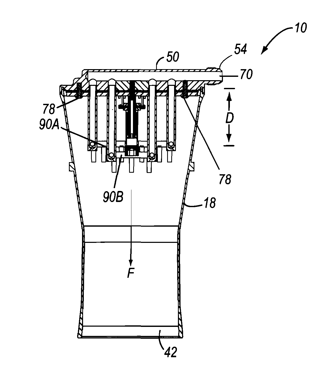
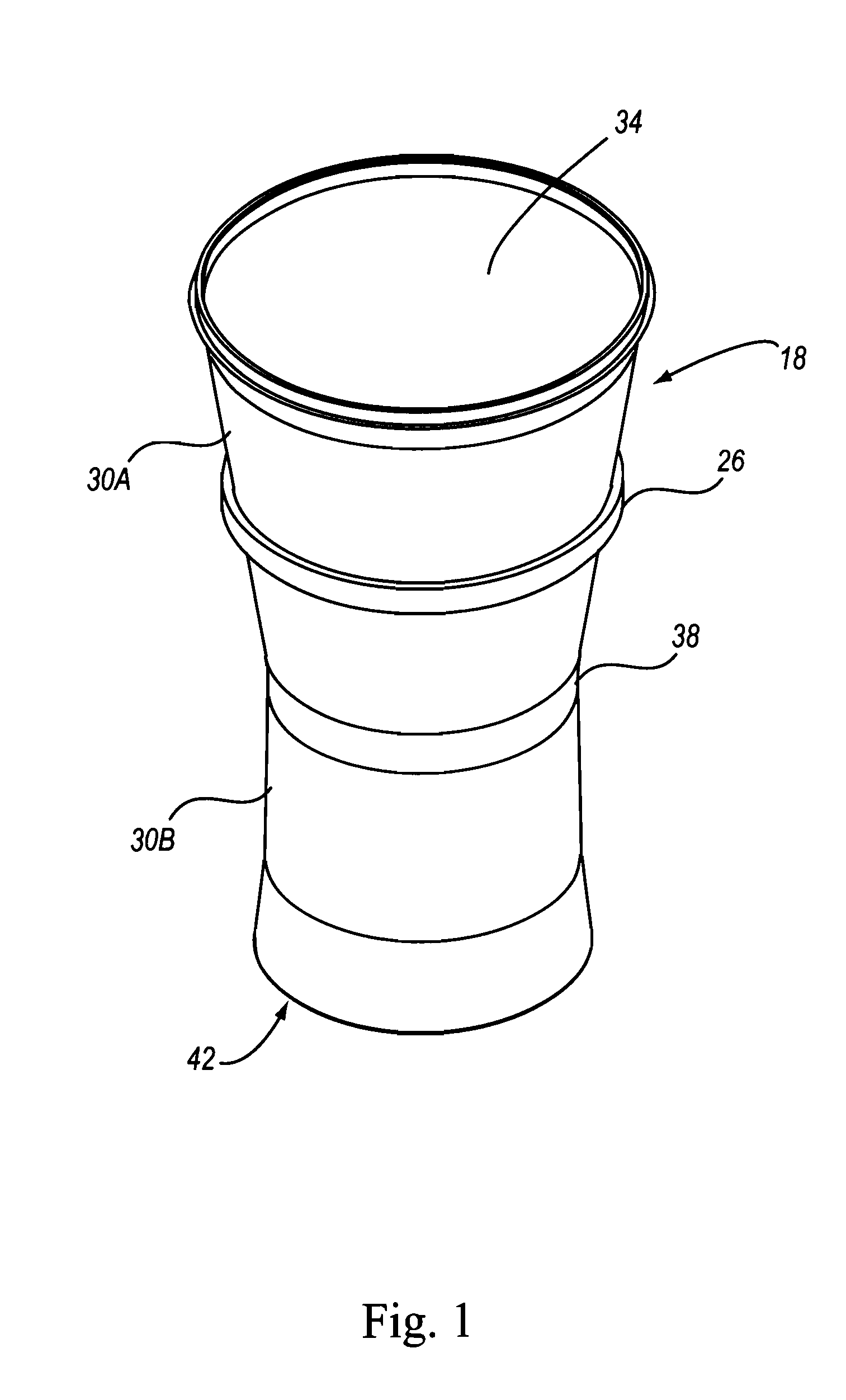
[0035]Illustrated in FIG. 9 is exemplary aspirator 10 consistent with the present invention. Aspirator 10 may be formed of housing 14 comprising body 18 and top cap assembly 22. Body 18 preferably has circular cross-section, albeit with diameter varying along its length L. Body 18 may, however, be shaped other than as depicted in FIGS. 1 and 9.

[0036]Contrasted with conventional aspirator housing bodies, body 18 beneficially may be formed as a monolithic structure of wound filaments rather than of one or more machined metal components. Filaments of carbon, aramids (including Kevlar), fiberglass, or otherwise may be wound to create body 18, providing the body 18 with satisfactory strength while reducing its weight substantially as compared with conventional metallic bodies.

[0037]Protruding externally from body 18 is flange 26. The flange 26 preferably is annular, although it may assume other shapes instead. Regardless of its shape, however, flange 26 is intended to engage a complement...


PUM


Abstract

Aspirators for inflating devices such as (but not limited to) aircraft evacuation slides and rafts are detailed. Housings of the aspirators may be made of wound filaments of composite materials, reducing their weight as compared to conventional metal structures. Such actions as reconfiguring and repositioning jet nozzles within the housings also contribute to enhancing performance of the aspirators.

Description

FIELD OF THE INVENTION[0001]This invention relates to devices used to inflate objects and more particularly, although not necessarily exclusively, to aspirators employed to control flow of inflation gas to evacuation slides and rafts.BACKGROUND OF THE INVENTION[0002]U.S. Pat. No. 4,368,009 to Heimovics, et al., whose contents are incorporated herein in their entirety by this reference, illustrates an aspirator intended to inflate structures including aircraft evacuation slides and rafts. The aspirator includes a housing made of fiber-reinforced plastic material and a pair of metal flapper valve plates. High-pressure gas enters the top of the housing in a single location along the (central) longitudinal axis of the housing, essentially perpendicular to a plane containing the flapper valve plates. The gas thereafter is exhausted by jets within the housing so as to create a localized region of low pressure therein, existence of which causes the flapper valve plates to open. Opening of ...

Claims


Application Information

Patent Timeline
Patent Type & Authority Patents(United States)
IPC IPC(8): F04F5/44F04F5/46F04F5/26
CPCB64D25/14F04F5/16Y10T137/87603Y10T137/87595
Inventor MCNEIL, DANIEL A.O'DONNELL, JOHNBROWN, FRANK
Owner AIR CRUISERS
Learn More