
Hydrocarbon treatment method and apparatus

a technology of hydrocarbon treatment and treatment method, applied in the direction of hydrogen separation using solid contact, gaseous mixture working up, machines/engines, etc., can solve the problems of reduced catalytic activity, reduced catalyst activity, and difficult removal of certain organic sulfur species that can be present in off-gas upstream of the reactor, so as to increase the production of additional hydrogen

Active Publication Date: 2012-11-27
PRAXAIR TECH INC
View PDF4 Cites 8 Cited by
  • Summary
  • Abstract
  • Description
  • Claims
  • Application Information

AI Technical Summary

Benefits of technology

This approach virtually eliminates catalyst deactivation, reduces the amount of catalyst required, and maintains low olefin and sulfur levels, enabling higher space velocities and increased hydrogen production while preventing carbon deposition on the reforming catalyst.

Problems solved by technology

Additionally, such streams have an organic sulfur content that is typically sufficiently high that the sulfur can also present a risk to the catalyst.
However, this being said, if the refinery gas contains more than 20 ppmv dry organic sulfur species, when the reactor is switched to oxidation mode, the high temperatures and the presence of sulfur will result in the deactivation of the catalyst that will result in a reduction in catalytic activity upon a return to the hydrogenation mode.
It is to be noted that certain organic sulfur species that can be present in an off-gas, such as mercaptans, sulfides and thiophenes, are particularly difficult to remove upstream of the reactor.

Method used


Image

  • Hydrocarbon treatment method and apparatus
  • Hydrocarbon treatment method and apparatus

Examples


Embodiment Construction

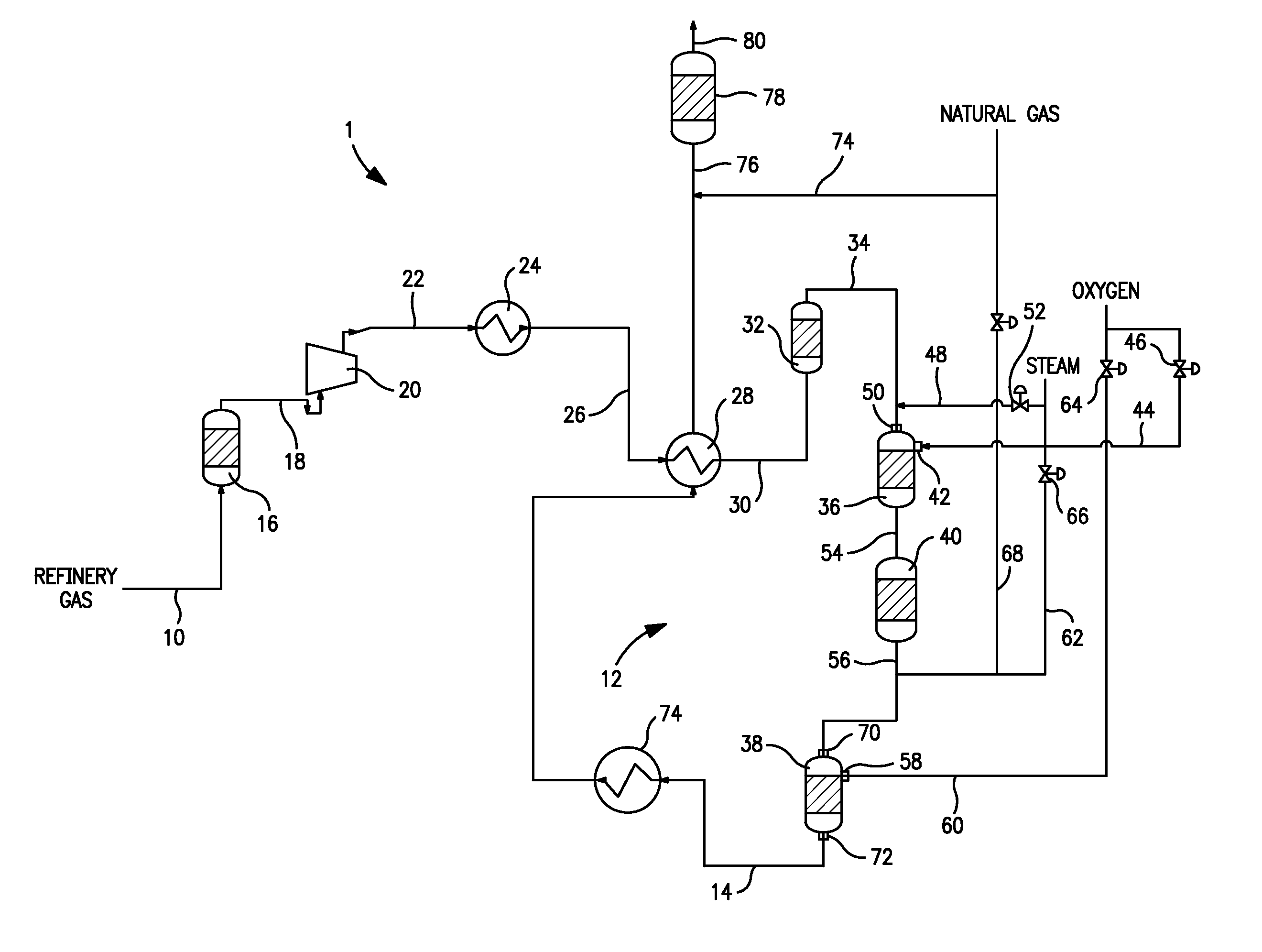
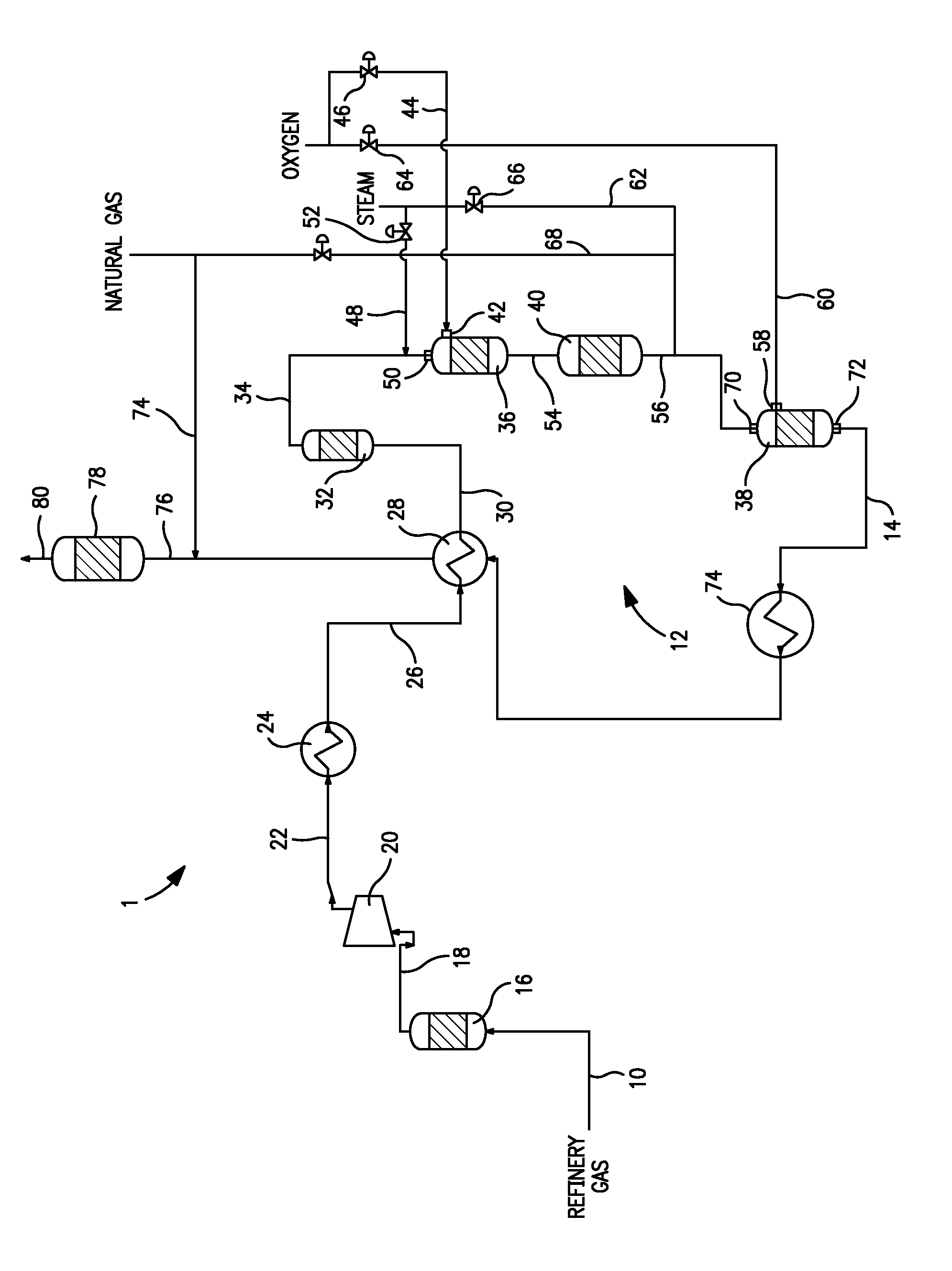
[0022]With reference to the sole FIGURE, an apparatus 1 is illustrated that receives an untreated hydrocarbon containing feed stream 10 in a reactor system 12 that is designed to produce a treated hydrocarbon containing stream 14 that has a lower concentration of olefins and organic sulfur species than the untreated hydrocarbon containing feed stream 10. The treated hydrocarbon containing stream 14 is used as a feed to a hydrogen plant that is provided with a steam methane reformer that, although not illustrated, is well known in the art and is fully described above.

[0023]The untreated hydrocarbon containing feed stream 10 can be a fluidic catalytic cracker (“FCC”) off-gas, a sweet refinery gas, coker off-gas or other type of hydrocarbon containing feed gas that contains a high amount of olefins and organic sulfur species. For example, the present invention would have equal applicability to an untreated hydrocarbon containing feed stream that constitutes an off-gas from steel making...


PUM

PropertyMeasurementUnit
temperatureaaaaaaaaaa

Abstract

A method and apparatus for producing a treated hydrocarbon containing stream for use as a feed to a hydrogen plant having a steam methane reformer in which an untreated hydrocarbon containing stream is introduced into two reaction stages connected in series to hydrogenate olefins and to convert organic sulfur species to hydrogen sulfide. The second of the two stages can also be operated in a pre-reforming mode to generate additional hydrogen through introduction of the oxygen and steam into such stage. A sulfur tolerant catalyst is used in both stages to promote hydrogenation and oxidation reactions. Sulfur is removed between stages by adsorption of the hydrogen sulfide to prevent deactivation of the catalyst in the second of the stages that would otherwise occur during operation of the second reaction stage in a pre-reforming mode of operation.

Description

FIELD OF THE INVENTION[0001]The present invention relates to a method and apparatus for treating an untreated hydrocarbon containing feed stream to produce a treated stream to serve as a feed to a steam methane reformer in which the olefin and organic sulfur contained in the untreated hydrocarbon containing feed stream are reduced with the use of a sulfur tolerant catalyst capable of promoting hydrogenation and oxidation reactions. More particularly, the present invention relates to such a method and apparatus in which the sulfur tolerant catalyst is located in two reactors of a reactor system having an adsorbent bed located between the reactors for removal of hydrogen sulfide produced from the conversion of the organic sulfur species in a first of the two reactors.BACKGROUND OF THE INVENTION[0002]Hydrogen is produced by steam methane reforming of a hydrocarbon containing feed in a steam methane reformer. A hydrocarbon containing stream, typically natural gas, is desulfurized and co...

Claims


Application Information

Patent Timeline
Patent Type & Authority Patents(United States)
IPC IPC(8): C10G45/04
CPCC10G70/02C01B3/382C01B3/56C10G70/046C10G2300/807C01B2203/0233C01B2203/0244C01B2203/0455C01B2203/0485C01B2203/1258C01B2203/142C10G2300/4018C10G2300/1025C10G2300/1088C10G2300/202C10G2300/207C10G2300/4006C01B3/34C10G45/04B01J8/04
Inventor DRNEVICH, RAYMOND FRANCISPAPAVASSILIOU, VASILISRAYBOLD, TROY M.PACOULOUTE, PERRY RAYMOND
Owner PRAXAIR TECH INC
Learn More