Fuel cell system

a fuel cell and system technology, applied in the field of fuel cell systems, can solve the problems of unnecessary separate heating of steam generators, and achieve the effects of reducing the size and complexity of the apparatus, improving the efficiency ratio, and reducing the complexity of the apparatus

Inactive Publication Date: 2012-11-20
WS REFORMER
View PDF11 Cites 0 Cited by
  • Summary
  • Abstract
  • Description
  • Claims
  • Application Information

AI Technical Summary

Benefits of technology

[0009]The high-temperature stack and preferably also the shift stage or the shift reactor are cooled in direct contact with evaporation channels and are thermostatically controlled with the aid of the steam pressure. Thus, the exhaust heat of at least the stack and, optionally, also that of the shift reactor is utilized, thus improving the efficiency ratio.
[0010]The size and complexity of the apparatus is reduced. In addition to the stack and the reformer, essentially only an air blower, a water pump, a condenser as well as a few valves and fittings are required. A separately heated steam generator is unnecessary.
[0011]Process control and process monitoring are particularly simple. There is only one control circuit for the temperature of the reformer. As regards the mass flows of fuel, air and water, a roughly proportional control is sufficient.
[0012]The electrical efficiency ratios for the total system are higher than in prior-art systems. In combination with a steam generator, it is possible to achieve an electrical efficiency ratio greater than 40% and, with the use of an autothermic reformer, up to 35%. In both cases, the total efficiency ratio for electrical current and heat is at approximately 100%.

Problems solved by technology

A separately heated steam generator is unnecessary.

Method used


Image

  • Fuel cell system
  • Fuel cell system
  • Fuel cell system

Examples


Embodiment Construction

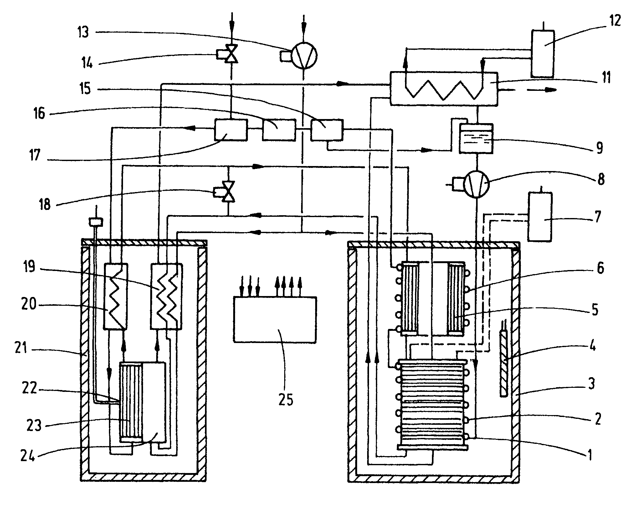
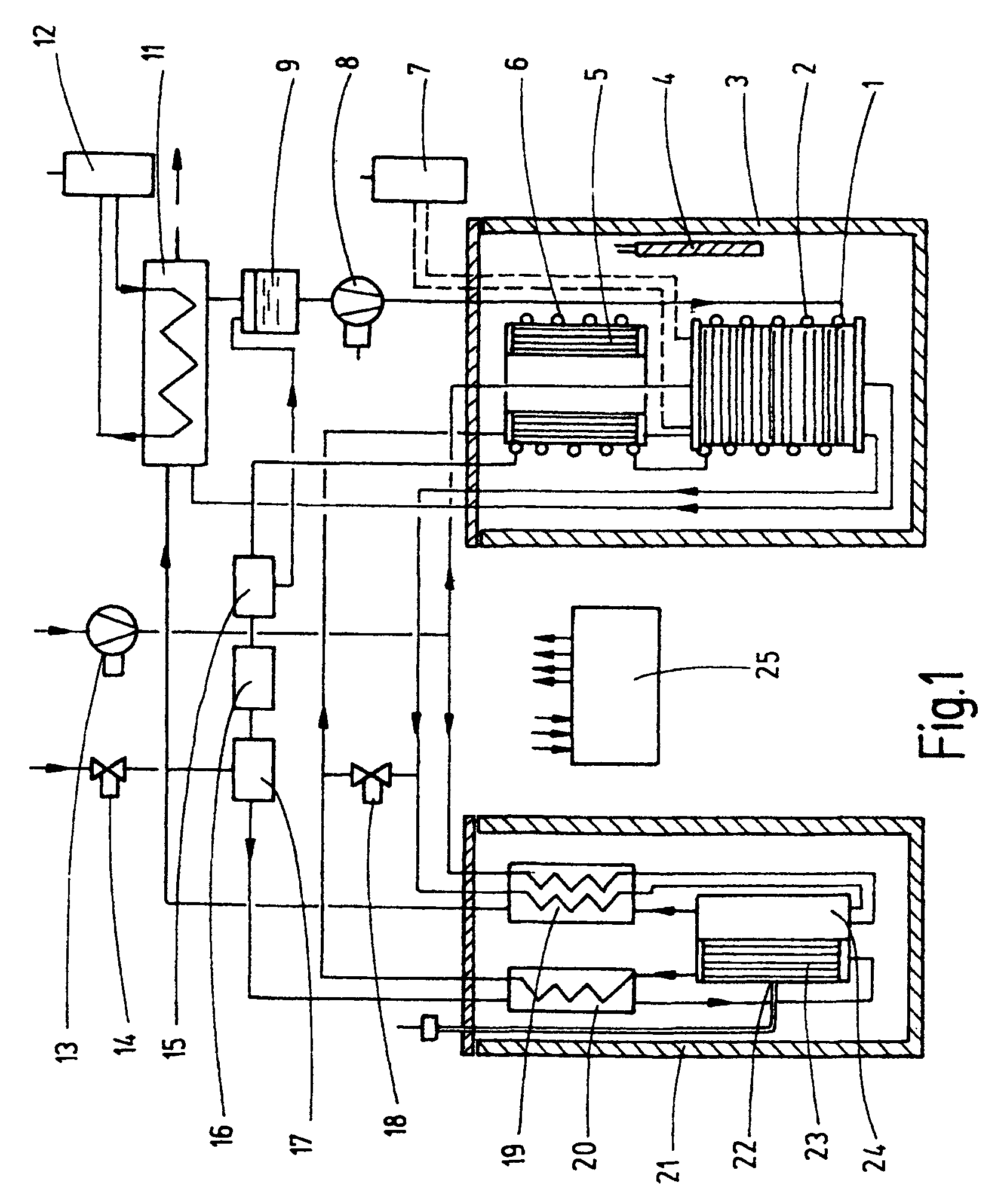
[0016]With reference to FIG. 1, for the generation of electrical energy, a fuel cell stack 1 is provided, said stack operating at a temperature above 100° C., preferably at about 120° C. or greater. The steam for the reformer is generated with the exhaust heat of the stack 1, said stack being thermostatically controlled with the steam pressure at the desired temperature. This is accomplished by evaporation channels 2, for example, in the form of one, or more evaporator tubes, for example, configured as tube coils, arranged directly on the stack 1, as well as by a pressure valve 16 in fluid communication with the outlet of the thusly created evaporator. In the simplest case, for example, in the case of constant output, the pressure valve is an adjustable valve. In the case of changing loads, the valve is, for example, a spring-biased pressure-maintaining valve. Alternatively, the thusly constructed pressure-maintaining device may also be represented by a controlled valve with an elec...


PUM

PropertyMeasurementUnit
operating temperatureaaaaaaaaaa
operating temperaturesaaaaaaaaaa
temperaturesaaaaaaaaaa

Abstract

The fuel cell system in accordance with the invention is used for the generation of current and heat from liquid and gaseous fuels. Said system comprises a reformer and a fuel cell stack having an operating temperature above 120° C. and providing exhaust heat that is utilized for the generation of steam in the evaporation channels (2). The evaporation channels (2) are arranged so as to be in direct thermal contact with the stack (1) that is to be cooled. A pressure-maintaining device at the outlet of the evaporation channels (2) is disposed to adjust the pressure in said channels to a value that results in the desired stack temperature.

Description

CROSS-REFERENCE TO RELATED APPLICATION[0001]This is a continuation-in-part application of pending international application PCT / EP2007 / 008311 filed Sep. 25, 2007 and claiming the priority of German application No. 10 2006 047 493.7 filed Oct. 5, 2006.BACKGROUND OF THE INVENTION[0002]Fuel cell systems are used for the conversion of energy from liquid and gaseous fuels into electrical current and heat. The conversion of energy takes place quietly in the fuel cell and at an efficiency ratio of between 50% and 60% during the conversion of chemical into electrical energy, depending on the selected current density in the cell. The advantages over an engine-driven current generator are particularly effective in the kW range in the case of small outputs as are required for the net-remote power supply and for decentralized power-heat coupling. Consequently, work to develop fuel cell systems is done worldwide, however, until now without any break-through on the market.[0003]The reasons theref...

Claims


Application Information

Patent Timeline
Patent Type & Authority Patents(United States)
IPC IPC(8): H01M8/06
CPCH01M8/04014H01M8/04089H01M8/0612H01M8/2475H01M8/04156Y02E60/50H01M8/24H01M8/04
Inventor WUNNING, JOACHIM A.SCHMID, HANS-PETER
Owner WS REFORMER
Why Eureka
Try Eureka