Radial work rotor engine

A rotary engine and engine casing technology, which is applied to machines/engines, mechanical equipment, gas turbine devices, etc., can solve the problems of low fuel explosive force, poor low-speed performance, poor sealing effect, etc., and achieve high fuel explosive force, improved low-speed performance, The effect of improving low-speed performance

Inactive Publication Date: 2012-12-05
席伟
View PDF0 Cites 0 Cited by
  • Summary
  • Abstract
  • Description
  • Claims
  • Application Information

AI Technical Summary

Problems solved by technology

[0002] At present, the engines of ground vehicles are mainly piston engines. Piston engines: first, they are stable at medium and low speeds, but their power decreases at high speeds, and their fuel efficiency is low; second, the reciprocating motion of pistons and connecting rods causes vibration, torque The alternating changes are large; the three structures are complex and difficult to manufacture
[0003] The turboshaft engine has large effective power and low vibration, and is widely used in the field of small and medium-sized aircraft. However, due to the continuous combustion working mode of the turboshaft engine, the combustion chamber cannot form an effective closed space, and the explosive power of the fuel is small, so a large amount of fuel is required. The continuous combustion of compressed air and fuel produces a large amount of high-temperature gas that acts on the entire turbine blade at the same time. The turbine speed is high, and the power is high. At the same time, the fuel consumption rate and speed are higher than that of the piston engine, and the low-speed performance is poor; The structure of the turbine blade makes it difficult to manufacture the turbine blade, resulting in a large amount of gas leakage and poor sealing effect, which wastes part of the power

Method used


Image

  • Radial work rotor engine
  • Radial work rotor engine
  • Radial work rotor engine

Examples


Embodiment Construction

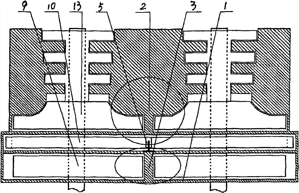
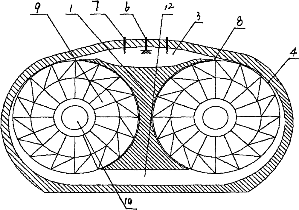
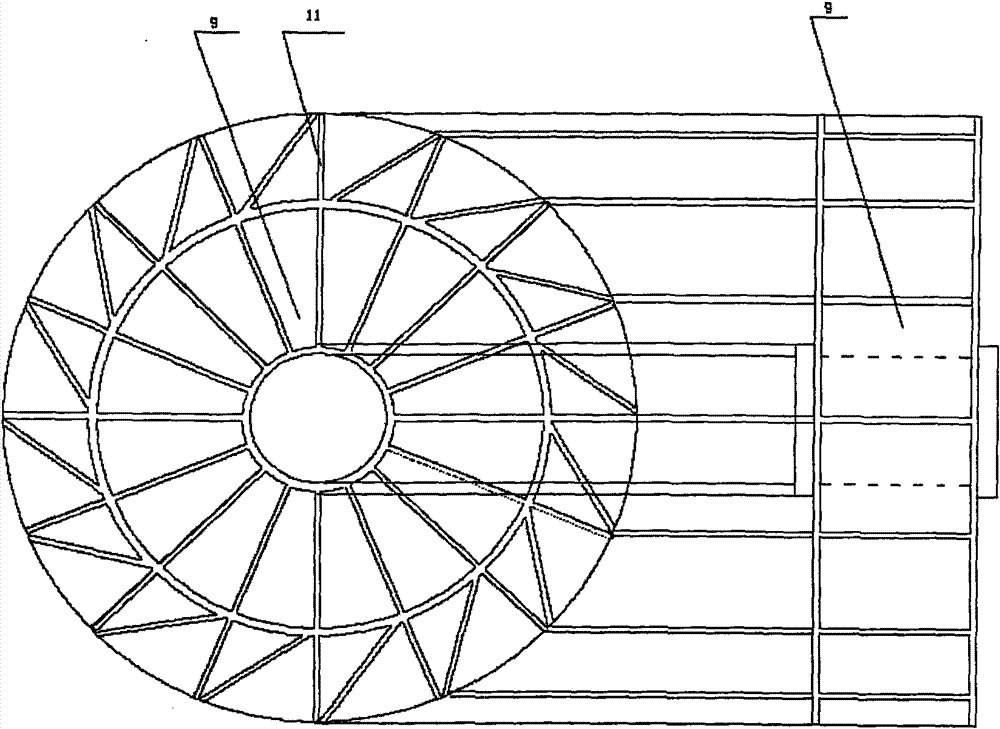
[0017] like Figure 1-3 As shown, a compressed air buffer chamber 2, a combustion chamber 3 and a rotor chamber 4 are formed in the engine casing 1, and the air outlet of the air compressor 13 communicates with the combustion chamber 3 through the compressed air buffer chamber 2 and the one-way valve 5, and the combustion chamber 3 Connect the fuel injection device 6 and the timing ignition device 7, the gas injection port 8 of the combustion chamber 3 communicates with the rotor chamber 4, the direction of the gas injection port 8 of the combustion chamber 3 is level with the inner diameter and outer edge of the rotor chamber 4, and the rotor 9 is installed in the rotor chamber 4. 9 consists of a rotor shaft 10 and rotor blades, the rotor blades 11 are concentrically distributed on the rotor shaft 10, the rotor shaft 10 is installed on the bearing of the engine casing 1, and the rotor shaft 10 is connected to the air compressor 13.

[0018] In the radial power rotor engine of...


PUM


Abstract

The invention discloses a rotary engine. A compressed air buffer chamber (2), a combustion chamber (3) and a rotor chamber (4) are formed in a shell (1) of the engine; an air outlet of an air compressor (13) is communicated with the compressed air buffer chamber (2) which is communicated with the combustion chamber (3) through a one-way valve (5); the combustion chamber (3) is connected with a fuel injection device (6) and a correct time ignition device (7); an air injection port of the combustion chamber (3) is communicated with the rotor chamber (4); a rotor (9) is arranged in the rotor chamber (4), and consists of a rotor shaft (10) and rotor blades (11); the rotor blades (11) are concentrically distributed on the rotor shaft (10) circularly; and the rotor shaft (10) is arranged on theshell of the engine and is provided with the air compressor (13). The rotary engine has simple structure, less parts, easy manufacture, stable performance, and simple maintenance, and can use variousfuels.

Description

technical field [0001] The invention belongs to the field of engines, and in particular relates to a radial power rotor engine. Background technique [0002] At present, the engines of ground vehicles are mainly piston engines. Piston engines: first, they are stable at medium and low speeds, but their power decreases at high speeds, and their fuel efficiency is low; second, the reciprocating motion of pistons and connecting rods causes vibration, torque The alternating change of three is large; the three structures are complex and difficult to manufacture. [0003] The turboshaft engine has large effective power and low vibration, and is widely used in the field of small and medium-sized aircraft. However, due to the continuous combustion working mode of the turboshaft engine, the combustion chamber cannot form an effective closed space, and the explosive power of the fuel is small, so a large amount of fuel is required. The continuous combustion of compressed air and fuel ...

Claims


Application Information

Patent Timeline
Patent Type & Authority Patents(China)
IPC IPC(8): F02C3/05F02C3/14F02C7/32
Inventor 席伟
Owner 席伟
Why Eureka
Try Eureka