
Apparatus for microwave heating of planar products

a technology for microwave heating and planar products, applied in microwave heating, electrical apparatus, electric/magnetic/electromagnetic heating, etc., can solve the problems of increasing processing time, increasing waveguide metal loss, and relatively slow process, and achieve uniform heating pattern

Inactive Publication Date: 2012-10-16
RAUTE OY
View PDF11 Cites 1 Cited by
  • Summary
  • Abstract
  • Description
  • Claims
  • Application Information

AI Technical Summary

Benefits of technology

Enables uniform heating of wider and thicker planar products, improving heating efficiency and reducing losses, allowing for a broader range of product thicknesses to be processed without changing the applicator's physical dimensions, and allowing for customizable heating patterns.

Problems solved by technology

This process is relatively slow, the processing time increasing with the thickness of the product.
1. The prior art structure is suitable only for heating products with very limited cross-section. The thickness of the heated product shall not exceed 10 to 15% of length of the longer side of the standard waveguide. The width of the heated product (along the longitudinal axis of the cavity) should not be longer than length of the longer side of the standard waveguide.
2. The heating occurs on a distance (along the direction of movement of the heated product) that is equal to the length of the shorter side of the waveguide.
3. Losses in the waveguide metal increases strongly when the operating frequency goes to the cut-off frequency of the cavity.
4. The cavity has a low Q factor. Insertion of the material to be heated into the cavity will additionally degrade the Q factor of the cavity. This results in non-uniform heating pattern and destruction of the resonant phenomenon.
GB1016435 notes as a disadvantage of GB893936 that adjustment of the tuning plunger and adjustment of the iris affect not only the tuning of cavity but also the standing wave pattern in the cavity, and this militates against the provision of the desired uniform distribution of the electric field along the central part of the cavity.
Moreover, tuning by means of a metal rod is questionable, because the metal rod may create with the walls of the waveguide cavity a TEM transmission line of substantially different wavelength than the waveguide, and it may further degrade heating uniformity.

Method used


Image

  • Apparatus for microwave heating of planar products
  • Apparatus for microwave heating of planar products
  • Apparatus for microwave heating of planar products

Examples


example 1

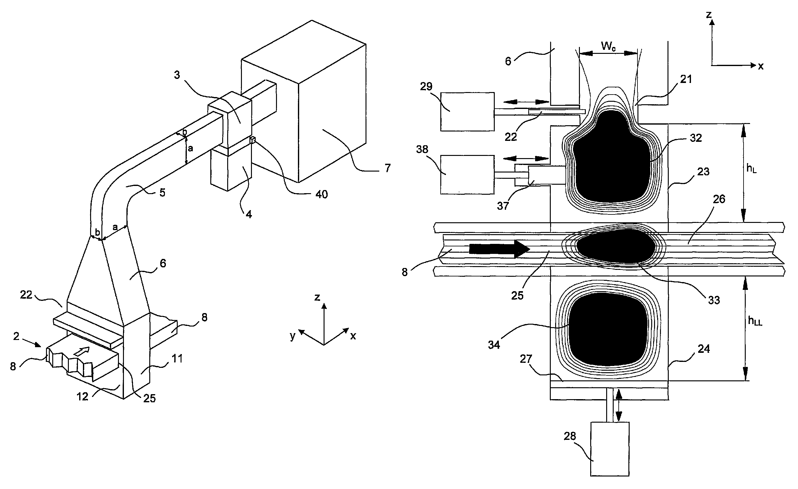
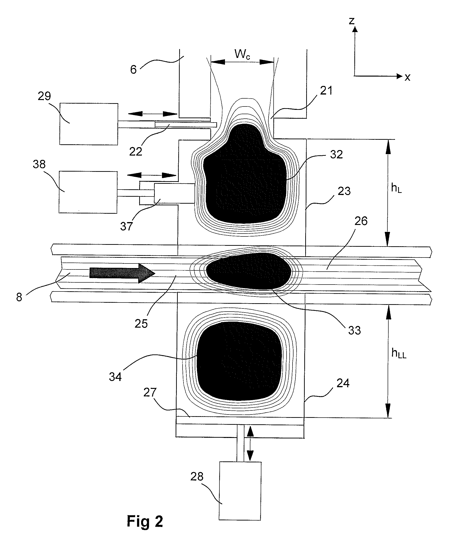
[0050]A two-and-half-wavelength applicator with 200 mm opening and the maximum electric field in the middle of the LVL (Laminated Veneer Lumber) panel was simulated with the upper part height hL=273 mm. The simulation results after a course tuning are presented in Table 1. These hLL and wc values may be used as default values. The results can be then enhanced by means of fine-tuning, as described above. FIG. 5 shows the average envelope electric field in x-z plane with 90 mm thick LVL.

[0051]

TABLE 1LowerCouplingReturnLVL'SpartwindowResonantlossthickness,height,width,frequency,at frt [mm]hLL [mm]wc [mm]fr [MHz][dB]90337158915−17.6120292156915−29.6150270156915−24.4185233156915−20.4

The example 1 shows that the heating apparatus according to the embodiment of the invention makes it possible to process the planar products in wide range of thickness up to any value between 50 mm to 200 mm or more. A preferred range of thickness is from about 90 mm to about 185 mm. The maximum thickness dep...


PUM


Abstract

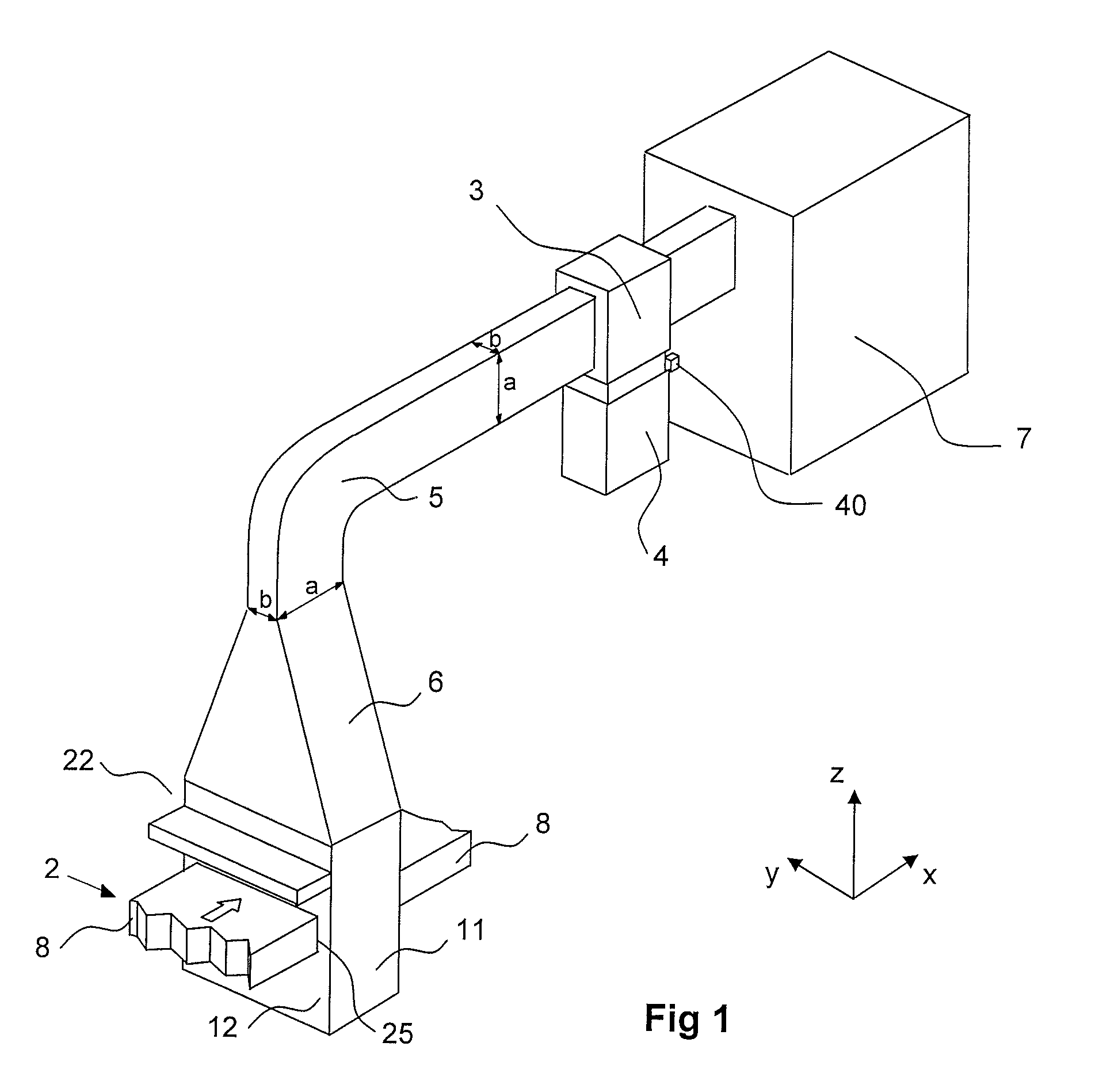
In a microwave heating apparatus, the fundamental TE10 mode of the standard waveguide (5) having a standard rectangular cross-section is fed into an elongated heating cavity (2) having an enlarged rectangular cross-section in which the shorter side of the standard waveguide is enlarged to a length which can accommodate the desired width of a board (8) to be heated. A pair of lateral slots (25) is provided parallel in the opposite enlarged walls (11) of the heating cavity (2) to form a track for the board (8) to travel across the cavity. As the initially longer sidewall (11) of the standard waveguide is unchanged, the fundamental mode is not affected but the electric field is uniformly distributed along the width of the board (8) traversing the electric field and the cavity. As a result, wider products can be heated and a more uniform heating pattern can be achieved.

Description

FIELD OF THE INVENTION[0001]The invention relates to microwave heating of planar products, particularly wood panels and boards.BACKGROUND OF THE INVENTION[0002]A pressed-wood composite product can be produced from a prepared pre-assembly mat which includes selected wood components along with intercomponent, heat-curable adhesive. A typical end product may, for example be plywood, or laminated veneer lumber (LVL), which, after production can be cut for use, or otherwise employed, in various ways as wood-based building components. The starter material would typically be, in addition to a suitable heat-curable adhesive, (a) thin sheet veneers of wood, (b) oriented strands (or other fibrous material) of smaller wood components, (c) already pre-made expanses of plywood which themselves are made up of veneer sheets or (d) other wood elements.[0003]In conventional LVL fabrication processing, LVL is typically made of glued, veneer sheets of natural wood, utilizing adhesives, such as urea-fo...

Claims


Application Information

Patent Timeline
Patent Type & Authority Patents(United States)
IPC IPC(8): H05B6/70H01P5/08
CPCH05B6/705H05B6/78H05B6/80
Inventor RISTOLA, PETEVILO, JAAKKOPIOTROWSKI, JERZY
Owner RAUTE OY
Learn More