
Data processing system

a data processing and data technology, applied in the field of data processing systems, can solve the problems of large space, difficult to detect psk modulated signals, current and area, etc., and achieve the effect of removing undesired high frequency contributions and increasing the accuracy of demodulation procedures

Inactive Publication Date: 2012-10-09
NXP BV
View PDF6 Cites 1 Cited by
  • Summary
  • Abstract
  • Description
  • Claims
  • Application Information

AI Technical Summary

Benefits of technology

The invention provides a device and method for processing an input signal with minimal effort. The device includes a delay unit, phase shifting unit, mixer unit, and extraction unit. The method involves delaying the input signal, phase shifting it with different phase values, and mixing it with other signals. The device and method can be implemented using software or hardware, and can be used in RFID and NFC applications. The technical effects of the invention include improved data processing efficiency, reduced silicon area and energy consumption, and simplified circuit design.

Problems solved by technology

The need of very high data rates (several Mbit / s) based on a 13.56 MHz carrier may make it necessary to use higher order modulation schemes, and therefore new receiver structures may be necessary as the actual concepts will not be able to handle the needs.
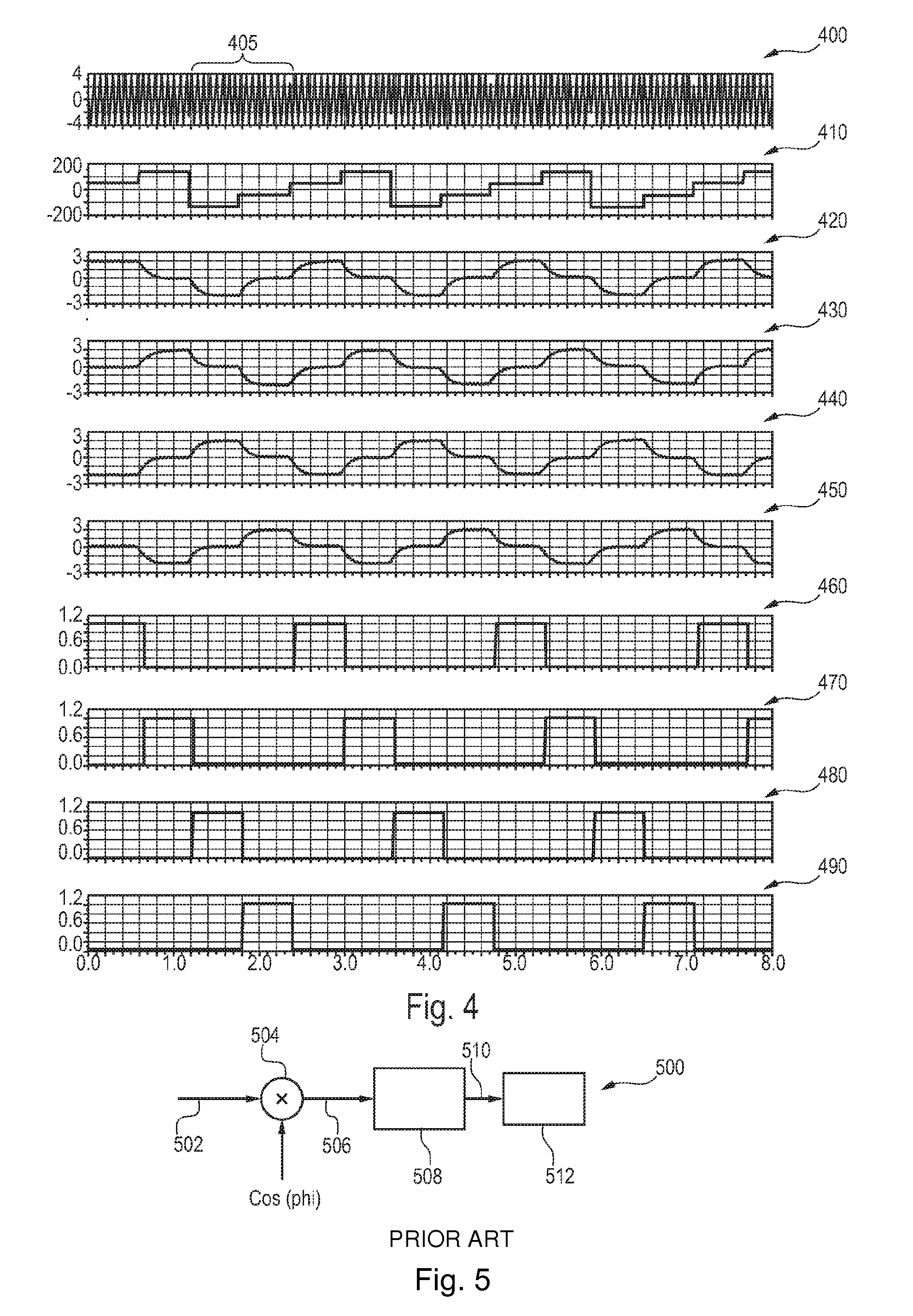
However, the demodulator circuit 500 shown in FIG. 5 requires a relatively large space on an integrated circuit and consumes a lot of energy during operation.
Furthermore, it may be difficult to detect PSK modulated signals, regarding current and area.

Method used


Image

  • Data processing system
  • Data processing system
  • Data processing system

Examples


Embodiment Construction

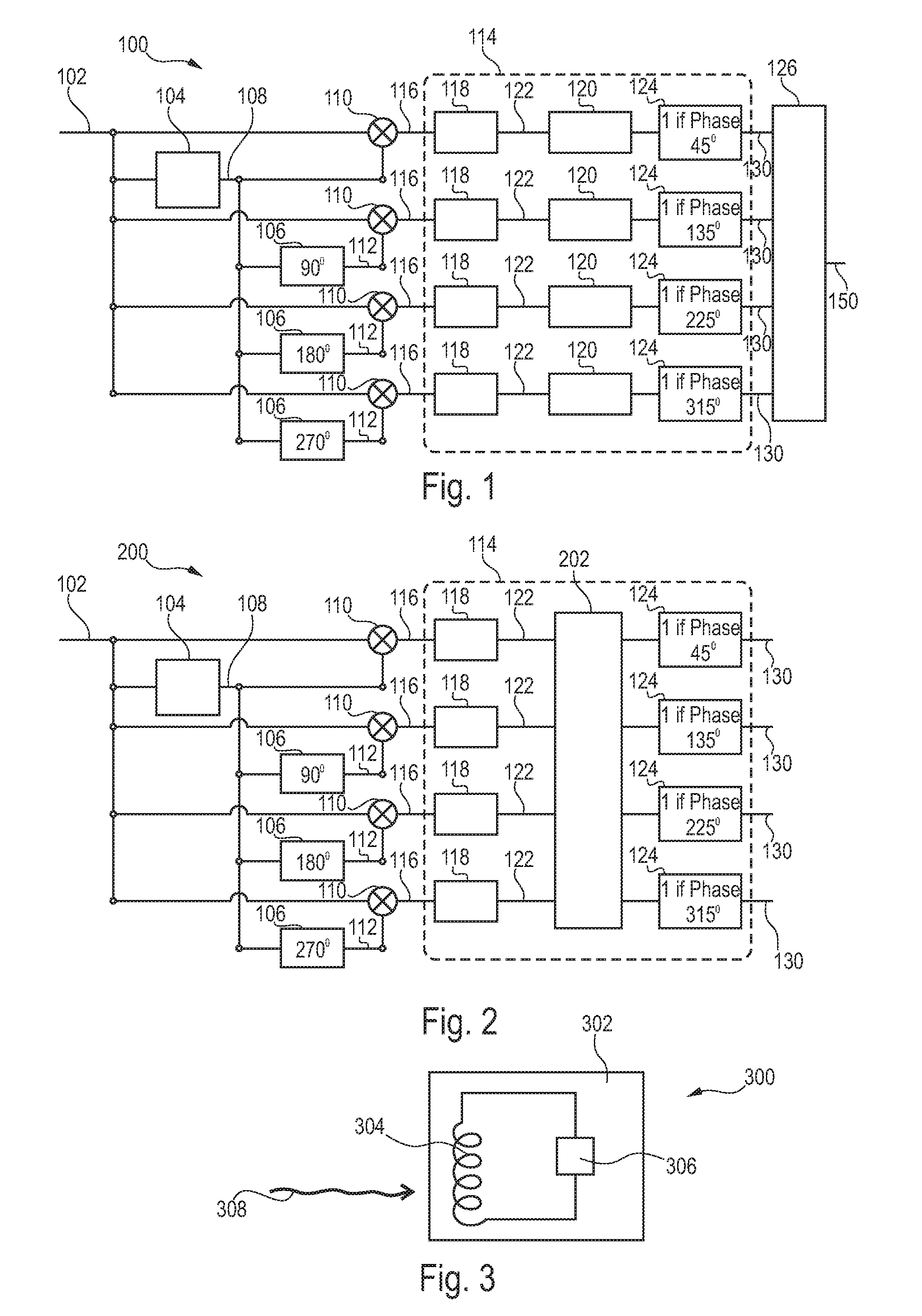
[0048]The illustration in the drawing is schematical. In different drawings, similar or identical elements are provided with the same reference signs.

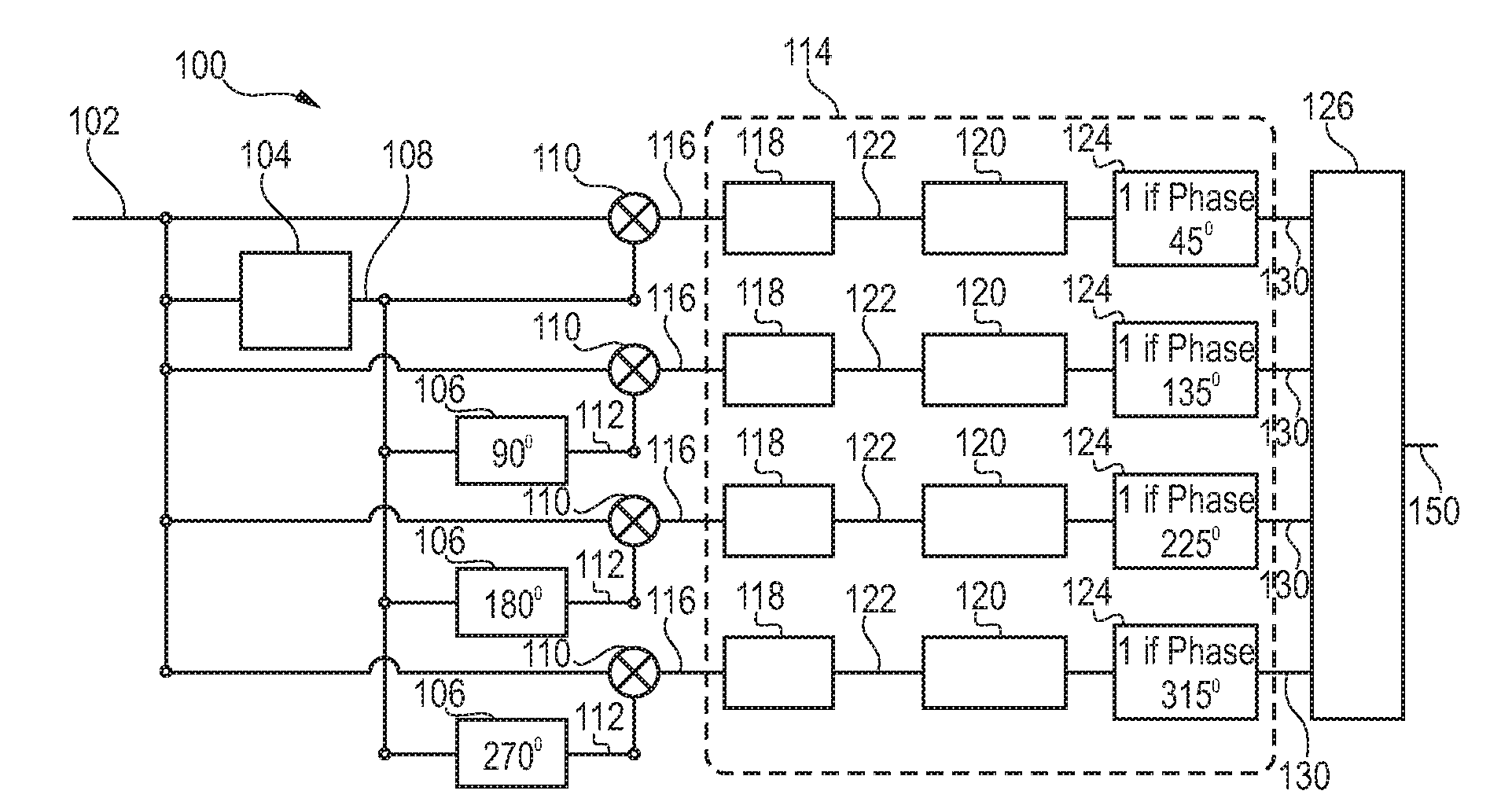
[0049]FIG. 1 illustrates a demodulator circuit 100 according to an exemplary embodiment of the invention.

[0050]The demodulator circuit 100 is adapted for demodulating a differential phase modulated input signal 102.

[0051]The input signal 102 is supplied to an input of a delay unit 104 for delaying the input signal 102 by a predefined delay time, particularly by one symbol.

[0052]A delayed signal 108 output by the delay unit 104 is supplied directly to a mixer unit 110 of a most upper signal processing path of the circuit 100 of FIG. 1. In parallel, the delayed signal 108 output by the delay unit 104 is supplied to a first phase shifting unit 106 shifting the signal 108 by a phase of 90°. The delayed signal 108 is further supplied to another phase shifting unit 106 performing a phase shift of 180°. Moreover, the delayed signal 108 is sup...


PUM


Abstract

A device (100) for processing an input signal (102), the device (100) comprising a delay unit (104) adapted for delaying the input signal (102) by a predefined delay time, at least one phase shifting unit (106) each adapted for phase shifting the delayed input signal (108) by an assigned phase value, a plurality of mixer units (110) each adapted for mixing the input signal (102) with the delayed input signal (108) or with one of the at least one phase shifted signal (112), and an extraction unit (114) adapted for extracting information from each of the mixed signals (116).

Description

FIELD OF THE INVENTION[0001]The invention relates to a device for processing an input signal.[0002]The invention further relates to a method of processing an input signal.[0003]Moreover, the invention relates to a program element.[0004]Furthermore, the invention relates to a computer-readable medium.BACKGROUND OF THE INVENTION[0005]The importance of automatic identification systems increases particularly in the service sector, in the field of logistics, in the field of commerce and in the field of industrial production. Further applications of identification systems are related to the identification of persons and animals.[0006]In particular contactless identification systems like transponder systems (for instance using an RFID tag) are suitable for a wireless transmission of data in a fast manner and without cable connections that may be disturbing. Such systems use the emission and / or absorption of electromagnetic waves, particularly in the high frequency domain (for instance at f...

Claims


Application Information

Patent Timeline
Patent Type & Authority Patents(United States)
IPC IPC(8): H04L27/22
CPCH03D3/007H04L27/2331
Inventor WITSCHNIG, HARALDAMTMANN, FRANZPATAUNER, CHRISTIAN
Owner NXP BV
Learn More