
Monochromator for charged particle beam apparatus

Active Publication Date: 2012-09-25
ASML NETHERLANDS BV
View PDF13 Cites 13 Cited by
  • Summary
  • Abstract
  • Description
  • Claims
  • Application Information

AI Technical Summary

Benefits of technology

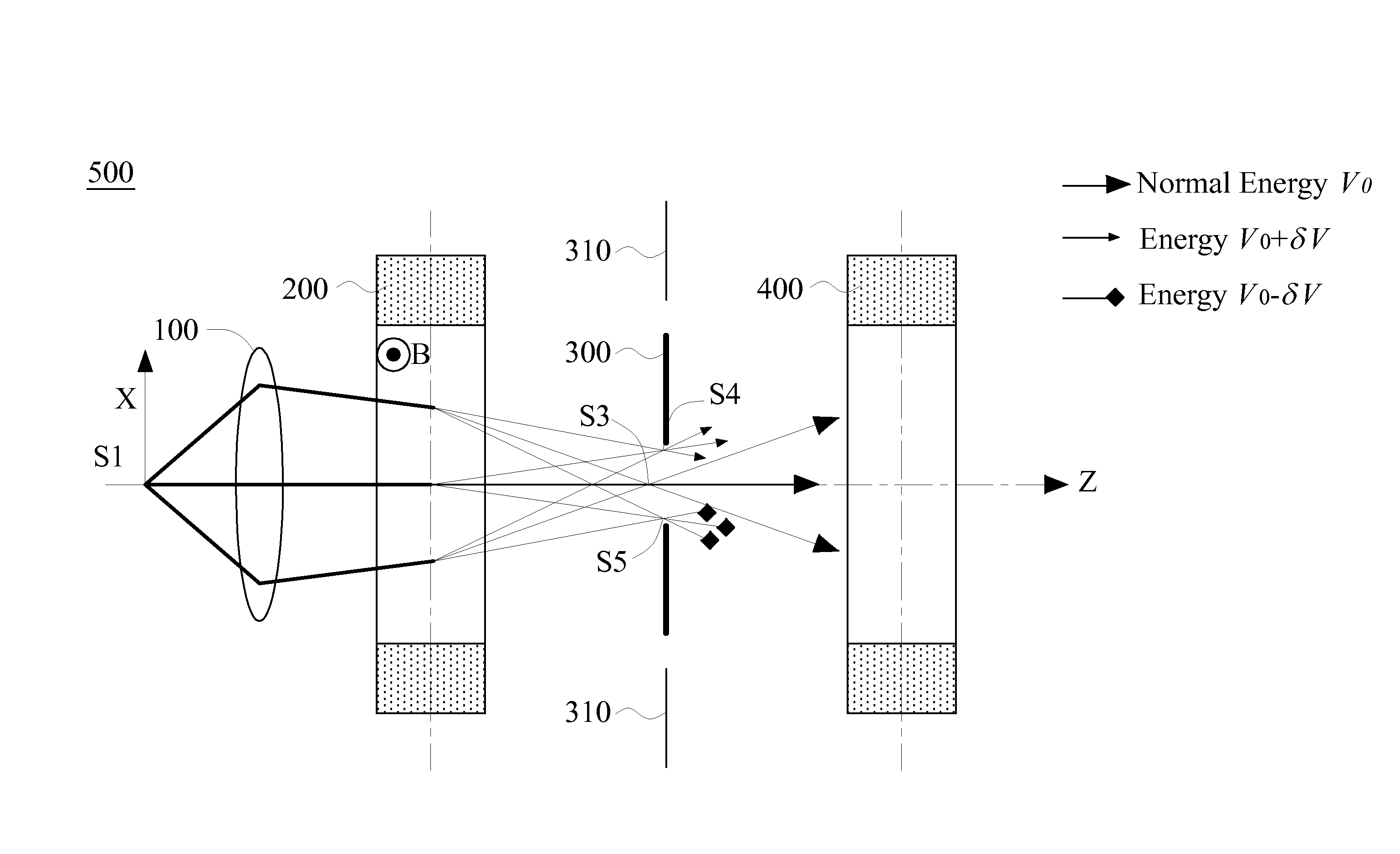
[0019]The object of this invention is to provide a monochromator for reducing energy spread of a primary charged particle beam in charged particle apparatus. By specifically forming a double symmetry in deflection dispersion and fundamental trajectory along a straight optical axis with respect to an energy-limit aperture, this monochromator makes an incident charged particle beam coming from a charged particle source exit it with a reduced energy spread as well as keeping the effective crossover diameter and propagation direction unchanged. Hence, this invention provides an effective way to improve the imaging resolution of Low-Voltage SEM and the related apparatuses which are based on LVSEM principle, such as the defect inspection and defect review in semiconductor yield management.
[0024]The present invention further provides an electron apparatus, which comprises an electron source for providing a primary electron beam propagating along a straight optical axis; a condenser, being aligned with the optical axis, for focusing the primary electron beam; an objective lens, being aligned with the optical axis, for focusing the primary electron beam onto a surface of a specimen which emanates secondary electrons; a stage for sustaining the specimen; a detector for receiving the secondary electrons; and a monochromator, being located between the electron source and the objective lens, for reducing an energy spread of the primary electron beam, wherein the monochromator comprises a first dispersion unit includes a first Wien filter and a first stigmator which compensates an astigmatism generated by the first Wien filter, a second dispersion unit includes a second Wien filter and a second stigmator which compensates an astigmatism generated by the second Wien filter, and a plate with an energy-limit aperture at central plane between the first and second dispersion units. Both of the first and second dispersion units being aligned with the optical axis. Inside the primary electron beam the electrons with a normal energy pass straight through said each dispersion unit and the electrons with energy deviations from the normal energy are deflected in a same direction as dispersion direction. A deflection angle of each electron depends on energy deviation thereof and a dispersion power of said each dispersion unit. Dispersion powers and dispersion directions of the first and second dispersion units are equal. The energy-limit aperture is aligned with the straight optical axis.

Problems solved by technology

However, the resolution will become worse because a low-energy electron beam forms a probe spot larger than a high-energy electron beam.
As an unignorable disadvantage, the energy depending filtering increases the source size.
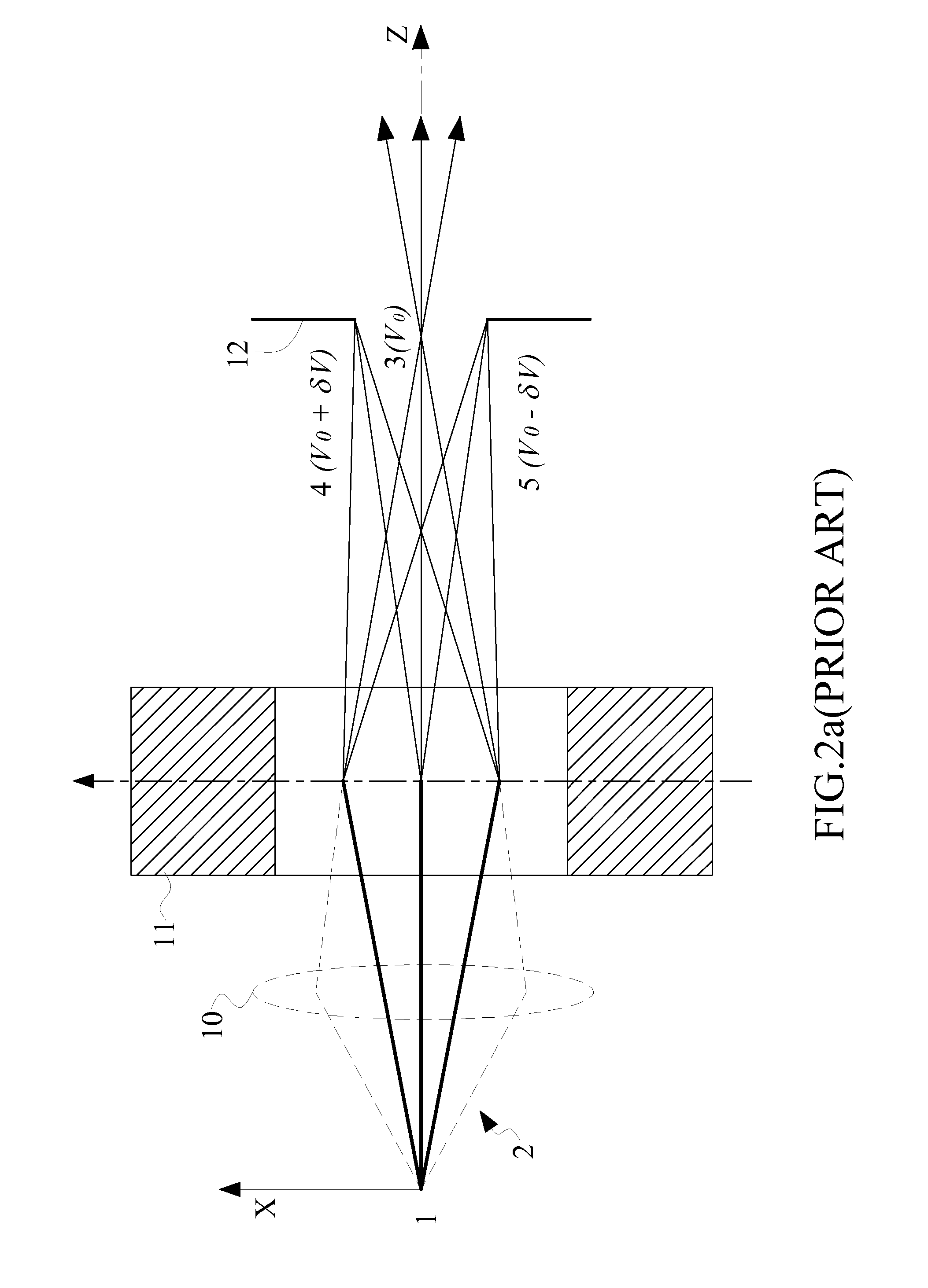
Increasing dispersion power of the Wien filter will increase deflection angle, but at the same time enhance its focusing effect which will in turn decrease the deflection angle and limits its achievable maximum of deflection angle.
Another unignorable disadvantage is the original source 1 is changed to be a larger virtual source from 14 to 15 for the following electron optics.
Although this method does not generate a real crossover, it generates a virtual crossover far away from the following electron optics which will incur large aberrations due to a large increase in beam size.

Method used


Image

  • Monochromator for charged particle beam apparatus
  • Monochromator for charged particle beam apparatus
  • Monochromator for charged particle beam apparatus

Examples


Embodiment Construction

[0041]Various example embodiments of the present invention will now be described more fully with reference to the accompany drawings in which some example embodiments of the invention are shown. Without limiting the scope of the protection of the present invention, all the description and drawings of the embodiments will exemplarily be referred to an electron source and scanning electron microscope. However, the embodiments are not to be used to limit the present invention to specific charged particle sources and specific electron microscope field.

[0042]The descriptions below will focus on using electron beam, which is a kind of charged particles. In the drawings, relative dimensions of each component and among every component may be exaggerated for clarity. Within the following description of the drawings the same reference numbers refer to the same components or entities, and only the differences with respect to the individual embodiments are described.

[0043]This invention provide...


PUM


Abstract

This invention provides a monochromator for reducing energy spread of a primary charged particle beam in charged particle apparatus, which comprises a beam adjustment element, two Wien-filter type dispersion units and an energy-limit aperture. In the monochromator, a double symmetry in deflection dispersion and fundamental trajectory along a straight optical axis is formed, which not only fundamentally avoids incurring off-axis aberrations that actually cannot be compensated but also ensures the exit beam have a virtual crossover which is stigmatic, dispersion-free and inside the monochromator. Therefore, using the monochromator in SEM can reduce chromatic aberrations without additionally incurring adverse impacts, so as to improve the ultimate imaging resolution. The improvement of the ultimate imaging resolution will be more distinct for Low-Voltage SEM and the related apparatuses which are based on LVSEM principle, such as the defect inspection and defect review in semiconductor yield management. The present invention also provides two ways to build a monochromator into a SEM, one is to locate a monochromator between the electron source and the condenser, and another is to locate a monochromator between the beam-limit aperture and the objective. The former provides an additional energy-angle depending filtering, and obtains a smaller effective energy spread.

Description

FIELD OF THE INVENTION[0001]The invention relates to a charged particle beam device, and more particularly to a monochromator for filtering a charged particle beam to a small energy spread. The invention also relates to a charged beam apparatus suitable for using such a device. However, it would be recognized that the invention has a much broader range of applicability.BACKGROUND OF THE INVENTION[0002]In the field of scanning electron microscope (SEM) and the related industrial fields which employ electron microscope principle to observe a sample, such as defect review and defect inspection for yield management in semiconductor manufacture, getting a specimen imaging with high resolution and low radiation damage has been required and pursued.[0003]The only remedy to reduce radiation damage on specimen is to use a low-energy (or typically called as low-voltage in SEM field) electron beam scanning (<5 keV) which limits the beam penetration beneath the specimen surface and the resid...

Claims


Application Information

Patent Timeline
IPC IPC(8): G21K1/08H01J37/21H01J37/20
CPCH01J37/05H01J37/28G21K1/093H01J2237/153H01J2237/049H01J2237/057
Inventor REN, WEIMINGCHEN, ZHONGWEI
Owner ASML NETHERLANDS BV
Learn More