
Hardware protection system for sensitive electronic-data modules protecting against external manipulations

a technology of electronic data modules and protection systems, applied in the direction of circuit security details, electrical apparatus construction details, support structure mounting, etc., can solve the problems of data not being manipulated, data being deleted immediately, and the loss of stored data in the electronic modul

Inactive Publication Date: 2012-09-18
SIEMENS AG
View PDF29 Cites 7 Cited by
  • Summary
  • Abstract
  • Description
  • Claims
  • Application Information

AI Technical Summary

Benefits of technology

"The patent describes a hardware protection system for electronic modules that can be integrated into an electronic-compatible installation. The system includes a circuit carrier that surrounds an interior space for components of a circuit to be protected. The conductor structures surrounding the interior space are designed to detect unauthorized external manipulations of the circuit. The circuit carrier can be a printed circuit board or a multilayered ceramic substrate with layers for wiring some of the components of the circuit and conductor structures. The system can be used in tachographs, journey data recorders, rail-bound or non-rail-bound motor vehicles, ATMs, devices for financial institutions, and airplanes. The method for producing the circuit carrier involves producing a circuit carrier with conductor structures surrounding the interior space for components of a circuit to be protected. The detectors can be integrated into the circuit to be protected."

Problems solved by technology

When attempting to open the package, the electrical conductors or resistance lines on the films are damaged and interrupted by force at the points at which the attacks take place, which results in the stored data in the electronic module being deleted immediately.
As a result, the data can not be manipulated and the attack can thus be recognized from the outside by corresponding control organs.
Two problems result with this method known from the related art.
On the other hand, the film is also often already damaged during assembly, thereby resulting in a high level of wastage.
In the case of an unauthorized attack on the circuit, the conductor structures are damaged, so that a contact is closed or interrupted and the attack on the circuit is thus detected.

Method used


Image

  • Hardware protection system for sensitive electronic-data modules protecting against external manipulations
  • Hardware protection system for sensitive electronic-data modules protecting against external manipulations
  • Hardware protection system for sensitive electronic-data modules protecting against external manipulations

Examples


Embodiment Construction

[0025]Reference will now be made in detail to the preferred embodiments of the present invention, examples of which are illustrated in the accompanying drawings, wherein like reference numerals refer to like elements throughout.

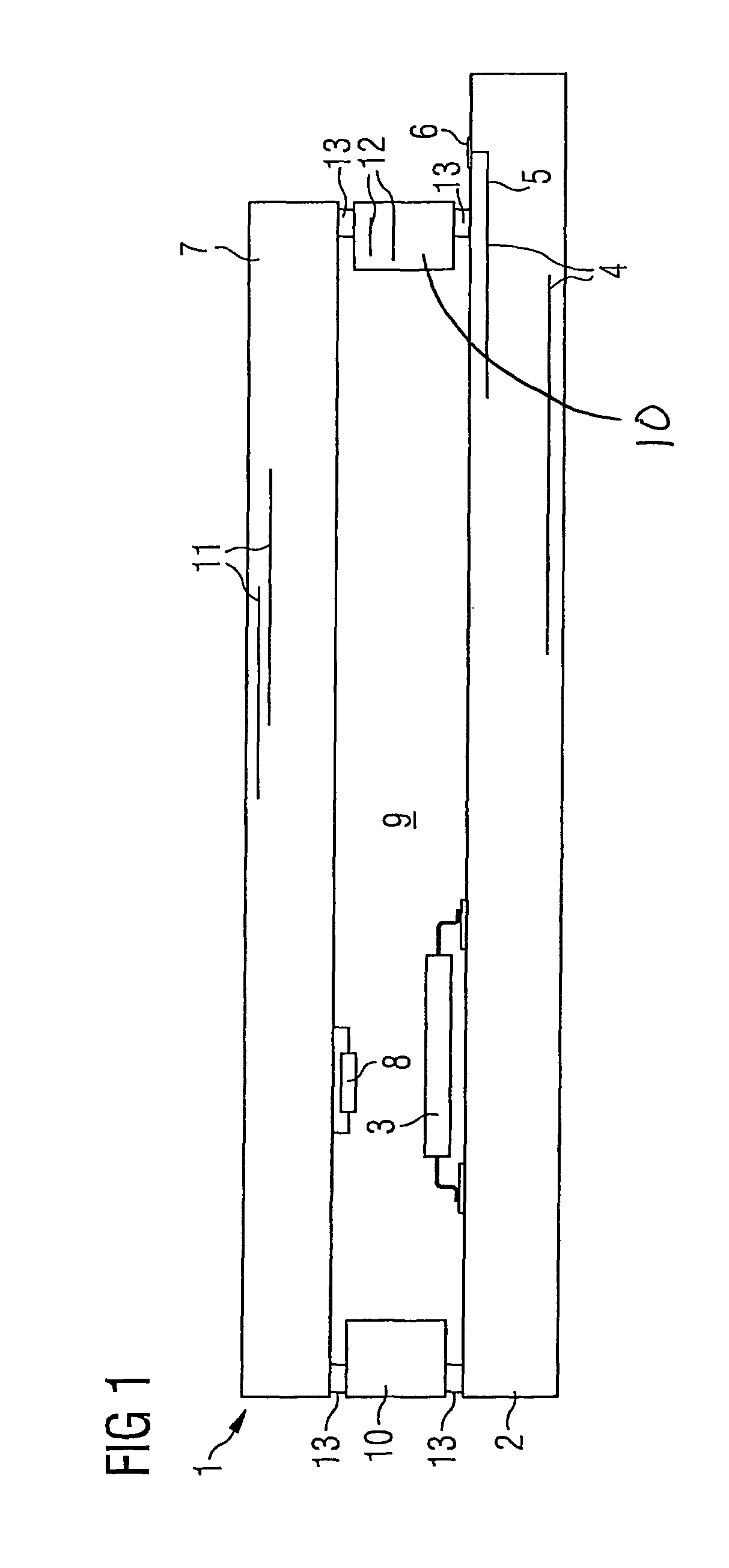
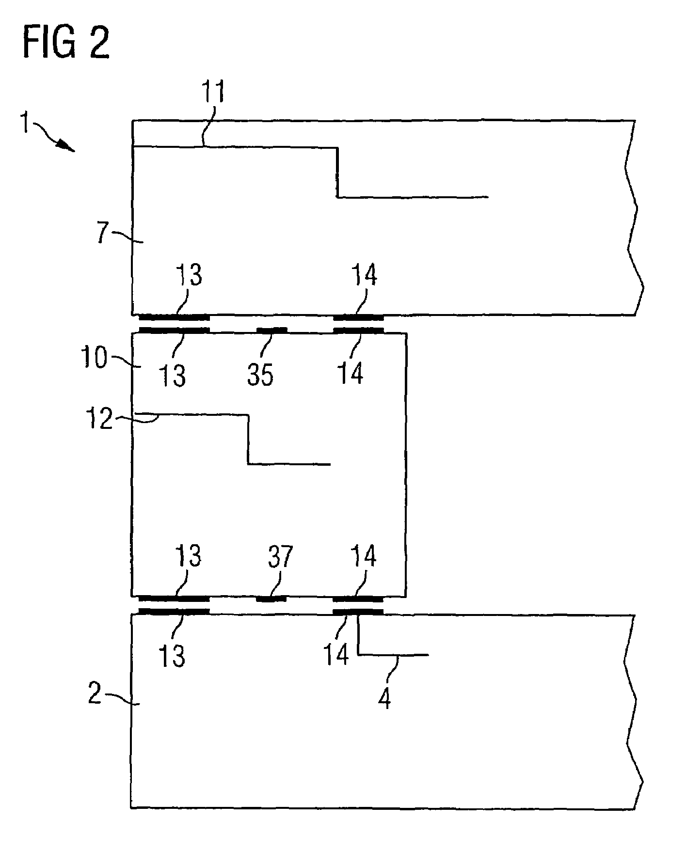
[0026]FIG. 1 shows a circuit carrier 1 with a first submodule in the form of a printed circuit board 2 having some components 3 of a circuit to be protected. The circuit board 2 has conductor structures 4 in the form of a protection layer as part of a multilayered wiring in order to detect attacks on the circuit to be protected. Furthermore, it has lead-throughs 5 for signal lines and voltage supply of the circuit to be protected outside the circuit carrier. These lead-throughs 5 pass through the conductor structures surrounding the interior space and terminate at a plug assembly point 6.

[0027]The circuit carrier 1 also has a further printed circuit board 7, which comprises further components 8 of the circuit to be protected.

[0028]The further components 8 of ...


PUM


Abstract

A hardware protection system is integrated into a circuit carrier. As a result, a sensor system, which is integrated into the circuit carrier in the form of printed circuit boards, which can be produced by means of the traditional high-tech printed circuit board technology and can be equipped with and processed on traditional insertion lines of electronic module installations, is obtained.

Description

CROSS REFERENCE TO RELATED APPLICATIONS[0001]This application is based on and hereby claims priority to PCT Application No. PCT / EP2005 / 053111 filed on Jun. 30, 2005, the contents of which are hereby incorporated by reference.BACKGROUND OF THE INVENTION[0002]Electronic modules for highly sensitive data processing and data security, as are used for instance in trip recorders for commercial vehicles but also in financial institutions, ATMs, airplanes and everywhere where sensitive data is managed, are to be protected in a hardware-specific fashion against external manipulations, such as chemical or physical attacks for instance (for instance mechanical, laser, fire etc.), so that data cannot be manipulated.[0003]A solution existed until now in which the electronic module to be protected was packed all around by what is known as a drilling protection film. Such a drilling protection film is produced for instance as a finished product by the company Gore or it is offered by the company F...

Claims


Application Information

Patent Timeline
Patent Type & Authority Patents(United States)
IPC IPC(8): H05K1/14G06F21/86
CPCG06F21/86H05K1/0275H05K1/144H05K1/145H05K2201/10151
Inventor WIMMER, ANTON
Owner SIEMENS AG
Learn More