Eureka AIR delivers breakthrough ideas for toughest innovation challenges, trusted by R&D personnel around the world.

Modular data center

Active Publication Date: 2007-10-09
GOOGLE LLC
View PDF6 Cites 513 Cited by
  • Summary
  • Abstract
  • Description
  • Claims
  • Application Information

AI Technical Summary

Benefits of technology

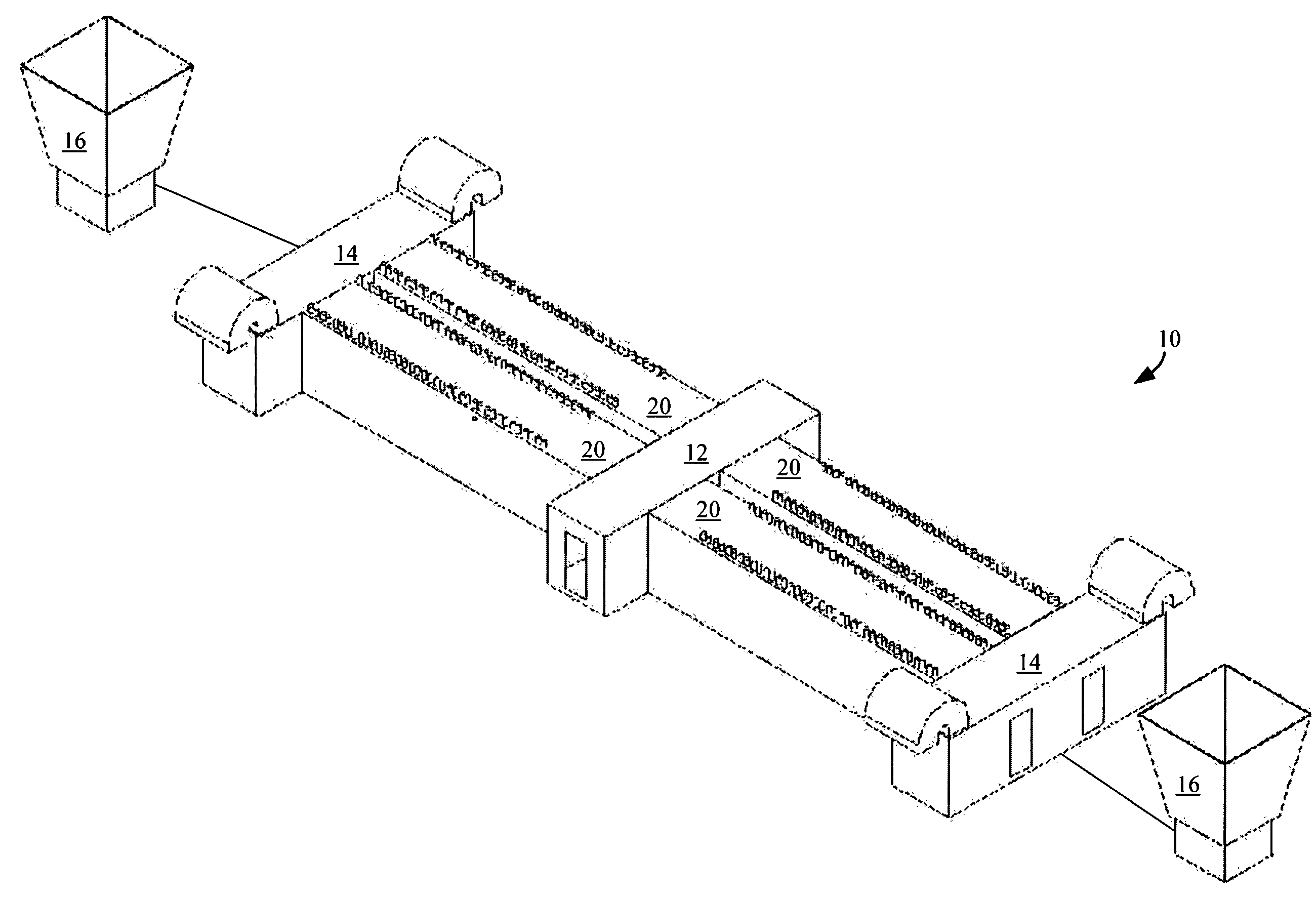
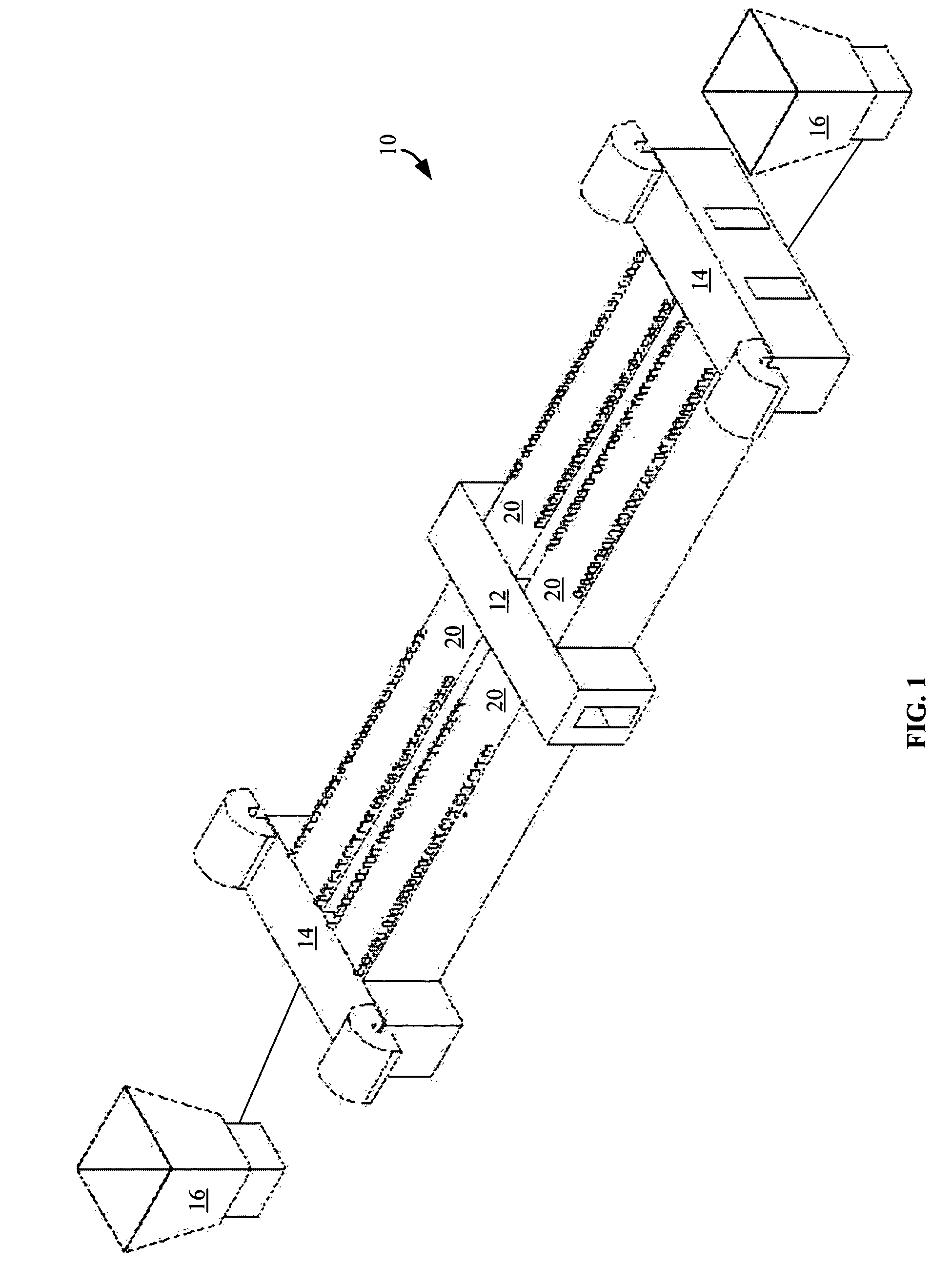
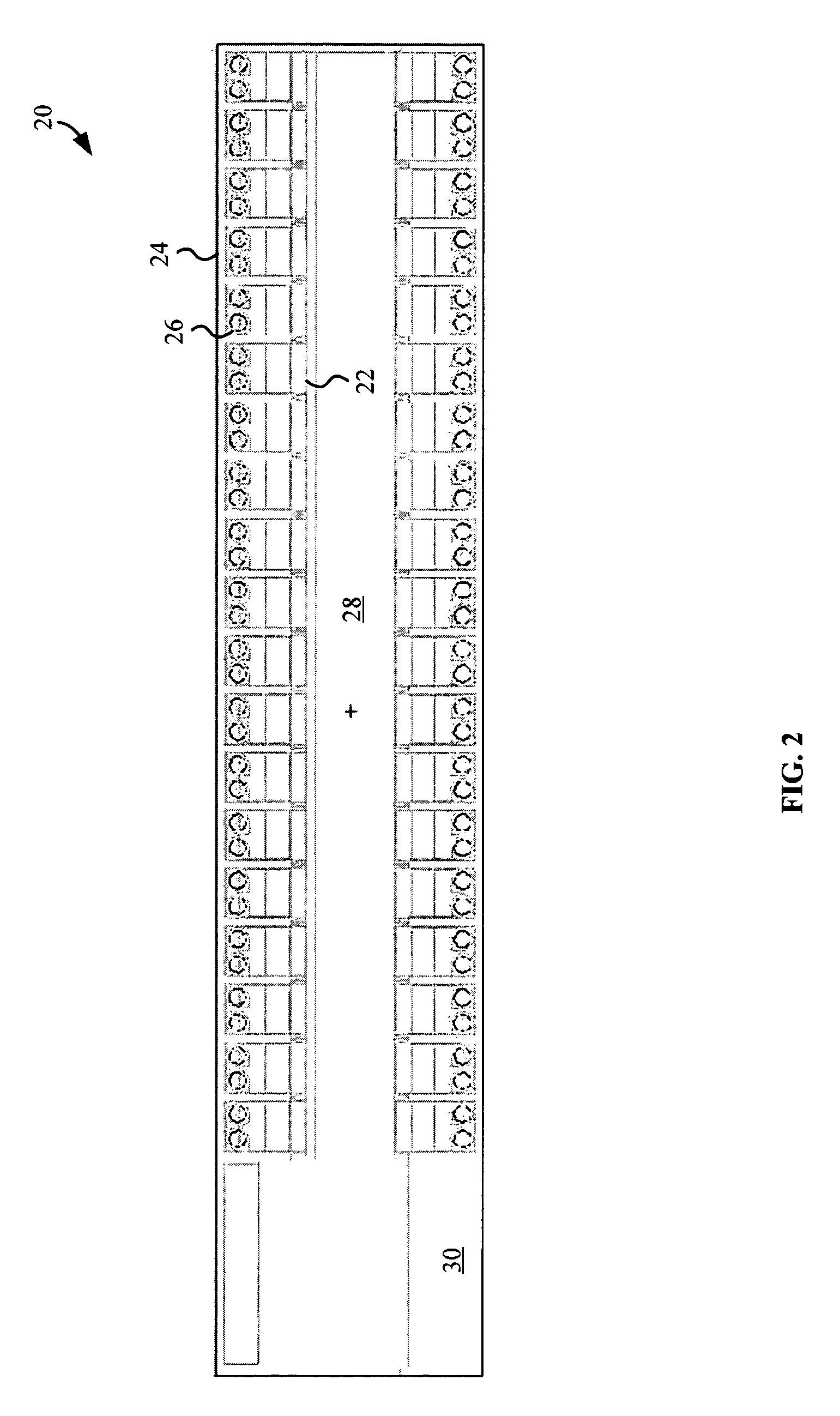
[0010]According to one embodiment, a modular data center generally includes a modular computing module including an intermodal shipping container and computing systems mounted within the container and configured to be shipped and operated within the container and a temperature control system for maintaining the air temperature surrounding the computing systems. The intermodal shipping container may be configured in accordance to International Organization for Standardization (ISO) container manufacturing standards or otherwise configured with respect to height, length, width, weight, and / or lifting points of the container for transport via an intermodal transport infrastructure. The modular design enables the modules to be factory built and easily transported to and deployed at a data center site.

Problems solved by technology

Typically, these processes are completed on-site at the colocation site by costly skilled tradesmen.
In addition, because installation at each site is customized to take into account site-specific constraints, i.e., site to site variations in data centers, installation difficulties arise and economies of scale cannot be fully exploited on installations.
Furthermore, because of the site-specific constraints, the processes are different for each site such that each site provides new opportunities for costly design and / or installation errors.
To further increase the costs, many colocations are relatively expensive to use or lease and typically are not setup for convenient operations or for easy deployment of large scale server racks, for example.
In large scale deployments, many potential opportunities to maximize power, cooling, ventilation, lighting, and space utilization, are not easily exploited at colocation sites.
Colocations also often have issues associated with power, cooling, and / or personnel.
Moreover, the available colocation sites may be limited.

Method used


Image

  • Modular data center
  • Modular data center
  • Modular data center

Examples


Embodiment Construction

[0021]Modular data centers with modular components suitable for use with rack or shelf mount computing systems, for example, are disclosed. The following description is presented to enable any person skilled in the art to make and use the invention. Descriptions of specific embodiments and applications are provided only as examples and various modifications will be readily apparent to those skilled in the art. The general principles defined herein may be applied to other embodiments and applications without departing from the spirit and scope of the invention. Thus, the present invention is to be accorded the widest scope encompassing numerous alternatives, modifications and equivalents consistent with the principles and features disclosed herein. For purpose of clarity, details relating to technical material that is known in the technical fields related to the invention have not been described in detail so as not to unnecessarily obscure the present invention.

[0022]FIG. 1 is a pers...


PUM


Abstract

Modular data centers with modular components suitable for use with rack or shelf mount computing systems, for example, are disclosed. The modular center generally includes a modular computing module including an intermodal shipping container and computing systems mounted within the container and configured to be shipped and operated within the container and a temperature control system for maintaining the air temperature surrounding the computing systems. The intermodal shipping container may be configured in accordance to International Organization for Standardization (ISO) container manufacturing standards or otherwise configured with respect to height, length, width, weight, and / or lifting points of the container for transport via an intermodal transport infrastructure. The modular design enables the modules to be cost effectively built at a factory and easily transported to and deployed at a data center site.

Description

BACKGROUND OF THE INVENTION[0001]1. Field of the Invention[0002]The present invention relates generally to computing data centers. More specifically, modular data centers with modular components suitable for use with rack or shelf mount computing systems, for example, are disclosed.[0003]2. Description of Related Art[0004]Many of today's more complex computing systems such as computer server systems are often rack-mounted systems in which a number of removable electronics modules, such as electronics trays, are positioned and stacked relative to each other in a shelf-like manner within a frame or rack. Rack-mounted systems allow the arrangement of several of the electronics modules in a vertical orientation for efficient use of space. Each electronics module can be slid into and out of the rack-mounting system.[0005]Each electronics module may correspond to a different server or each electronics module may hold one or more components of a server. Examples of electronics modules incl...

Claims


Application Information

Patent Timeline
IPC IPC(8): F25D23/12F25D17/06H05K7/20
CPCH05K7/1497G06F1/16H01R43/26
Inventor WHITTED, WILLIAM H.AIGNER, GERALD
Owner GOOGLE LLC
Why Eureka
Eureka Blog
Learn More