Pneumatic control device for supplying hydraulic fluid

a pneumatic control device and hydraulic fluid technology, applied in the direction of piston pumps, non-mechanical valves, servomotors, etc., can solve the problems of reducing the space available for other components, and affecting the operation of pneumatic control devices. , to achieve the effect of reducing the number of components, reducing the probability of malfunction, and reducing the length of the tub

Active Publication Date: 2012-09-11
WANG WEN FENG
View PDF13 Cites 0 Cited by
  • Summary
  • Abstract
  • Description
  • Claims
  • Application Information

AI Technical Summary

Benefits of technology

[0007]The invention has the following advantages. The occupied space of the assembled pneumatic control device is greatly decreased because the piston, the poppet and associated components thereof are assembled in the base, the cylinder, and the body. Moreover, the number of the components is decreased. Tube length is shortened. The probability of malfunction is decreased. It is easy for maintenance. Finally, the assembly is facilitated.

Problems solved by technology

However, the well known pneumatic control device suffers from a couple of disadvantages.
This in turn reduces space available for other components.
As a result, the conventional pneumatic control devices are bulky.

Method used


Image

  • Pneumatic control device for supplying hydraulic fluid
  • Pneumatic control device for supplying hydraulic fluid
  • Pneumatic control device for supplying hydraulic fluid

Examples


Embodiment Construction

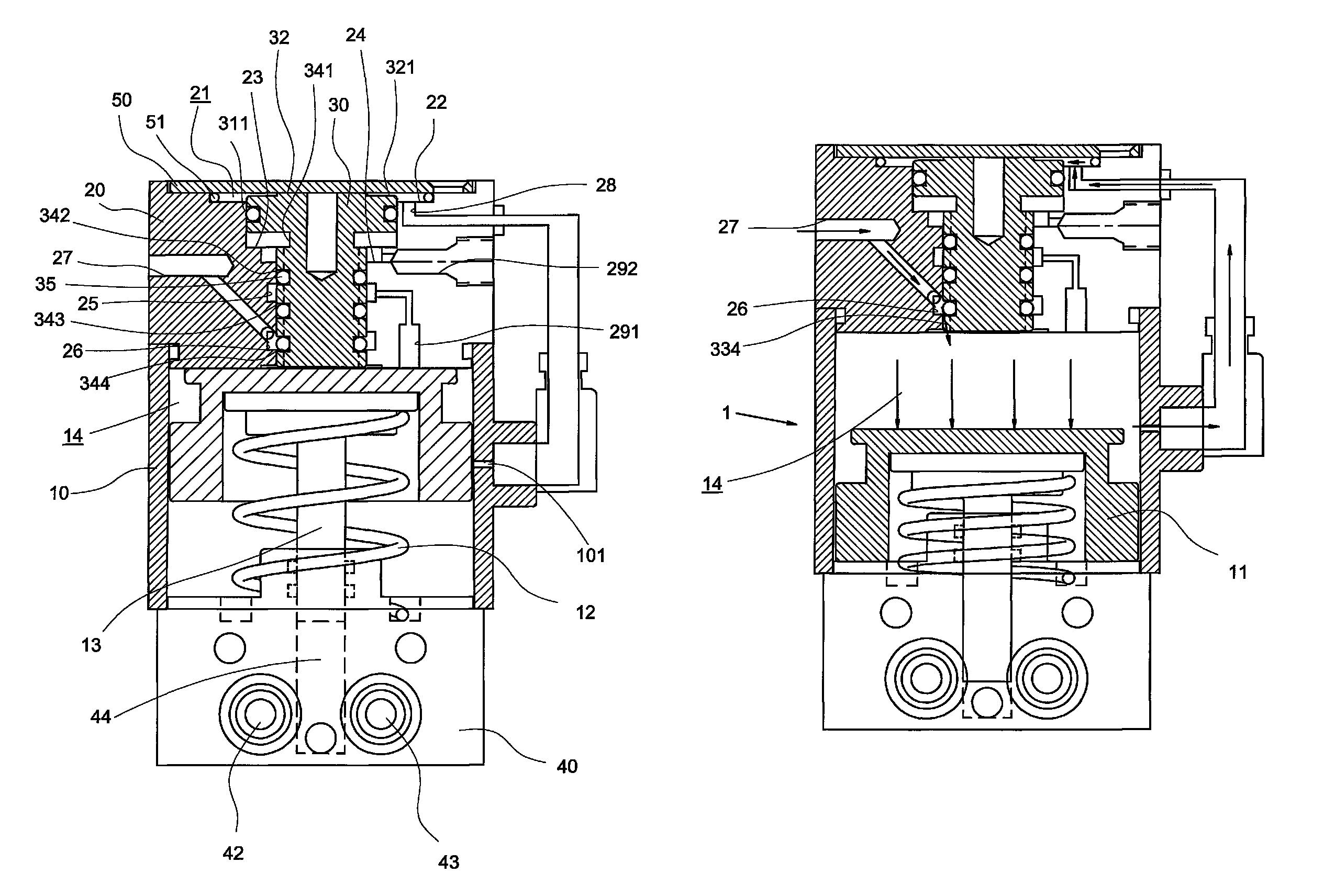
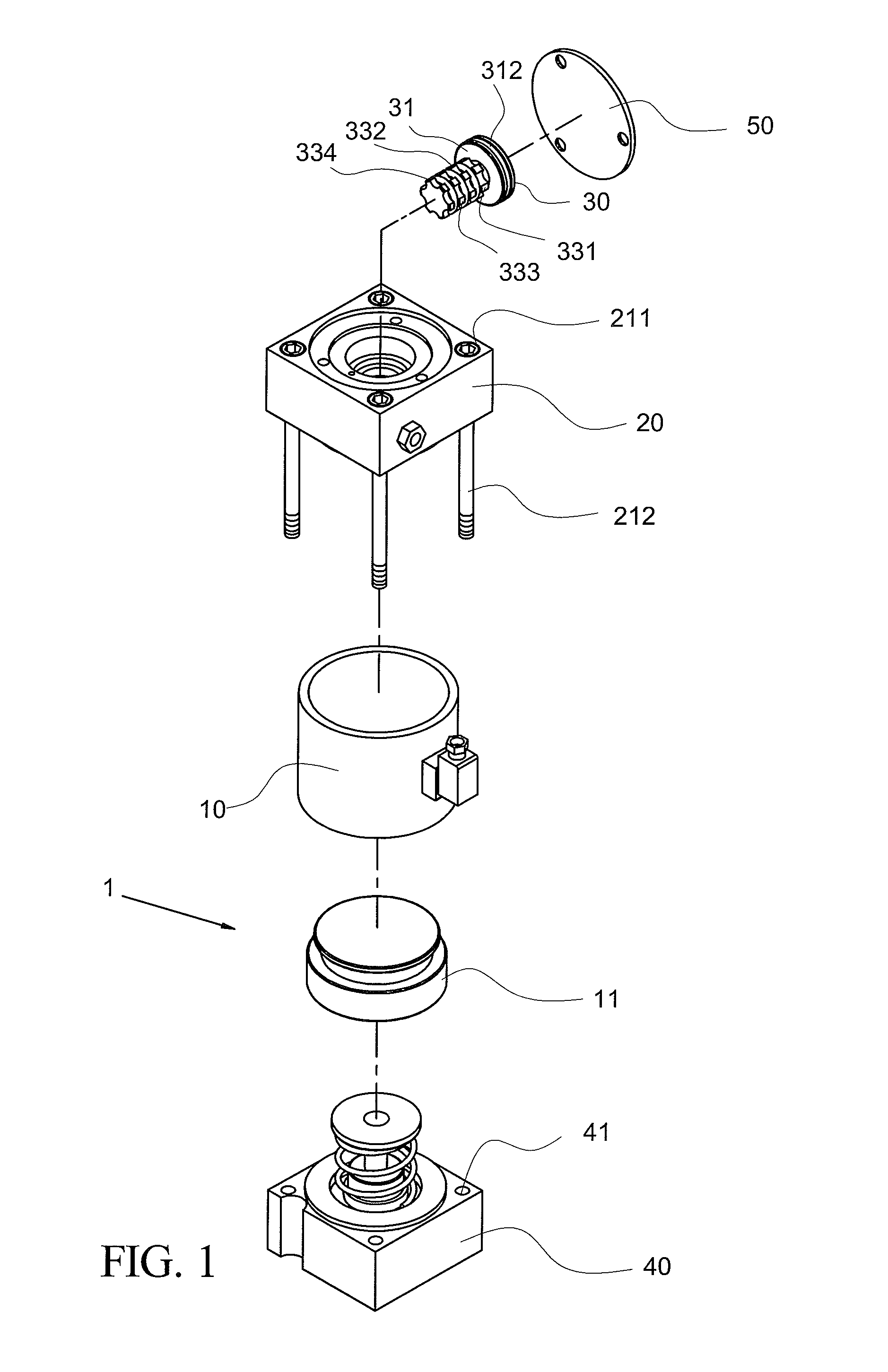
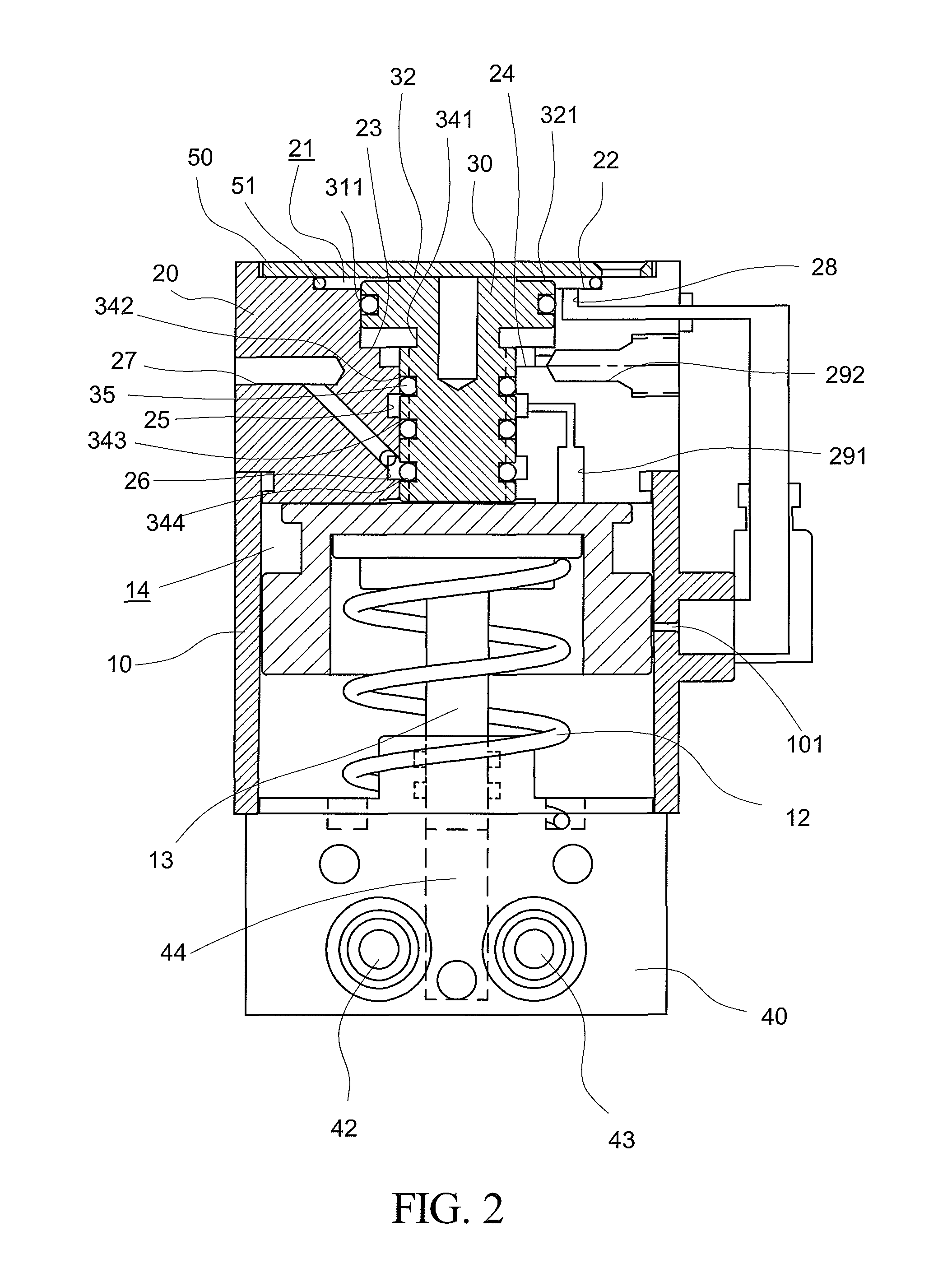
[0013]Referring to FIGS. 1 to 5, a pneumatic control device 1 for supplying hydraulic fluid in accordance with a preferred embodiment of the invention is shown. The pneumatic control device 1 is mounted to one end of a machine vise 60. The pneumatic control device 1 comprises the following components as discussed in detail below.

[0014]A hollow cylinder 10 comprises a piston 11 provided in a chamber 14 in the cylinder 10 so as to separate the chamber 14 from a central reservoir 44 (for storing hydraulic fluid) in a rectangular base 40. A rod 13 has an enlarged head attached to a recessed bottom of the piston 11 and a bottom disposed in the reservoir 44. A bias spring (e.g., compression spring) 12 is biased between the head of the rod 13 and the base 40 so that the piston 11 may move forth and back in the cylinder 10 when the bias spring biased rod 13 moves as described in detail later.

[0015]A rectangular body 20 comprises a central stepped-diameter passageway 21 including first, seco...


PUM


Abstract

A pneumatic control device includes a base comprising a reservoir, a first check valve for only allowing hydraulic fluid to flow into the reservoir, and a second check valve for only allowing the fluid to flow out of the reservoir; a hollow cylinder comprising a spring biased piston; a body mounted to the cylinder thereunder and releasably secured to the base, the body comprising a stepped-diameter passageway with a poppet mounted therein; and a cover releasably secured onto the poppet. In response to feeding pressurized air into the cylinder, the fluid in the reservoir flows out during a first stroke of the piston, and the fluid is sucked back into the reservoir during an opposite second stroke of the piston. In one embodiment, the fluid is for actuating a machine vise.

Description

BACKGROUND OF THE INVENTION[0001]1. Field of Invention[0002]The invention relates to pneumatic and hydraulic devices and more particularly to a pneumatic control device for supplying hydraulic fluid to, for example, a machine vise.[0003]2. Description of Related Art[0004]Conventionally, a control device for a pneumatic control device for supplying hydraulic fluid is disposed externally. For example, conventional electrical drills and machine vases each has an external, pneumatic control device (e.g., poppet valve and associate components) for supplying hydraulic fluid thereto.[0005]However, the well known pneumatic control device suffers from a couple of disadvantages. For example, the size of the device is greatly increased. This in turn reduces space available for other components. As a result, the conventional pneumatic control devices are bulky. Thus, a need for improvement exists.SUMMARY OF THE INVENTION[0006]It is therefore one object of the invention to provide a pneumatic co...

Claims


Application Information

Patent Timeline
Patent Type & Authority Patents(United States)
IPC IPC(8): F04B17/00
CPCF15B11/0725
Inventor WANG, WEN-FENG
Owner WANG WEN FENG
Why Eureka
Try Eureka