
Roll line in a continuous caster

a continuous casting machine and rolling line technology, applied in the direction of couplings, manufacturing tools,foundry moulding apparatus, etc., can solve the problems of more space-consuming solutions, and achieve the effects of saving space, improving operational reliability, and positive impact on the environmen

Inactive Publication Date: 2012-09-11
AB SKF
View PDF11 Cites 0 Cited by
  • Summary
  • Abstract
  • Description
  • Claims
  • Application Information

AI Technical Summary

Benefits of technology

This solution enhances operational reliability, reduces environmental impact, saves space, and optimizes lubricant usage by maintaining lubrication within the roll line, ensuring continuous performance without the need for external lubrication systems.

Problems solved by technology

If the ring is made in for instance two pieces, it may lead to a more space consuming solution.

Method used


Image

  • Roll line in a continuous caster
  • Roll line in a continuous caster
  • Roll line in a continuous caster

Examples


Embodiment Construction

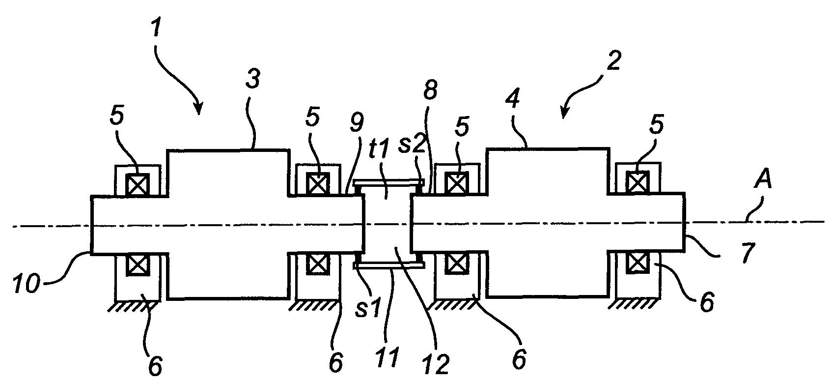
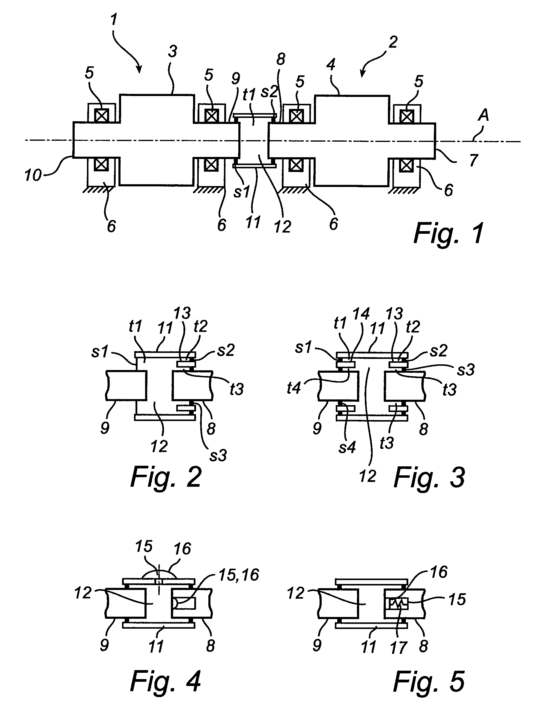
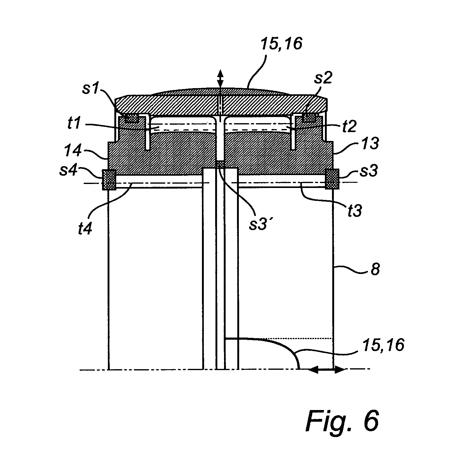
[0038]FIG. 1 shows a cross section of a roll line according to the present invention. The roll line comprises at least two segment roll lines 1, 2 for transporting steel and arranged along one axial line A. Each segment roll line comprising a roll body 3, 4 to be in supportive contact with the steel, bearings 5 for supporting the roll body 3, 4, bearing housings 6 for housing the bearings 5, the roll body 3, 4 having two shaft ends 7, 8, 9, 10. The roll line further comprises a ring 11 presenting a through-hole. A first and a second adjacent shaft ends 8, 9 of the at least two segment roll lines 1, 2 are at least partly inside the through-hole of the ring 11. The first and second adjacent shafts ends 8, 9 are connected to at least one torque transferring element t1. The at least one torque transferring element t1 may be designed in different ways. For instance, it may be splines / toothings, side face splines or a male / female coupling. Side face splines means that the splines connecti...


PUM

PropertyMeasurementUnit
torqueaaaaaaaaaa
transfer torqueaaaaaaaaaa
pressureaaaaaaaaaa

Abstract

A roll line in a continuous caster is disclosed. It comprises at least two segment roll lines (1, 2) for transporting steel. Each segment roll line (1, 2) comprises a roll body (3, 4), bearings (5) for supporting the roll body (3, 4), bearing housings (6). The roll body (3, 4) has two shaft ends (7, 8, 9, 10), and a ring (11). Adjacent shaft ends (8, 9) of segment roll lines (1, 2) are at least partly inside the through-hole of the ring (11) and the adjacent shafts ends (8, 9) are connected via torque transferring element (t1). There is a closed compartment (12) for receiving lubricant for lubricating the torque transferring element (T1). The closed compartment (12) is in the through-hole and is sealed off by sealing elements (s1, s2) located between the ring (11) and circumferential surfaces of the first and second adjacent shaft ends (8, 9).

Description

TECHNICAL FIELD OF THE INVENTION[0001]The invention concerns continuous casting of steel. More specifically, the invention concerns a roll line in a continuous casting machine.BACKGROUND OF THE INVENTION[0002]Continuous casting of steel is a demanding process, characterized by high temperatures and large temperature variations. Furthermore, water cooling of the steel strand and steam results in a very corrosive environment. For driven roll lines, where roll lines are divided into segments, there is a need to connect the segments by mechanical couplings. These mechanical couplings are lubricated, most often by grease. The couplings are continuously lubricated in order to secure and maintain the performance of the coupling.[0003]In the art it is well known to make use of lubricating systems to accommodate a suitable lubrication. A lubricating system comprises pipes for inlet and outlet of the lubricant, lubricant pumps etc. A limitation with lubricating systems is that there is a risk...

Claims


Application Information

Patent Timeline
Patent Type & Authority Patents(United States)
IPC IPC(8): B22D11/128
CPCB22D11/1287F16D1/10F16D3/848F16D3/72F16D2300/06F16D2001/103
Inventor JOHANSSON, MATSJOHANSSON, DANIEL
Owner AB SKF
Learn More