
System and method of prebias for rapid power amplifier response correction

a technology of prebias and power amplifier, applied in the direction of amplifiers with semiconductor devices/discharge tubes, gain control, transmission, etc., can solve the problems of unwanted unwanted changes in the gain or phase response of pa during the transition period, and inability to provide additional forward curren

Active Publication Date: 2012-09-04
SIGE SEMICON
View PDF2 Cites 27 Cited by
  • Summary
  • Abstract
  • Description
  • Claims
  • Application Information

AI Technical Summary

Benefits of technology

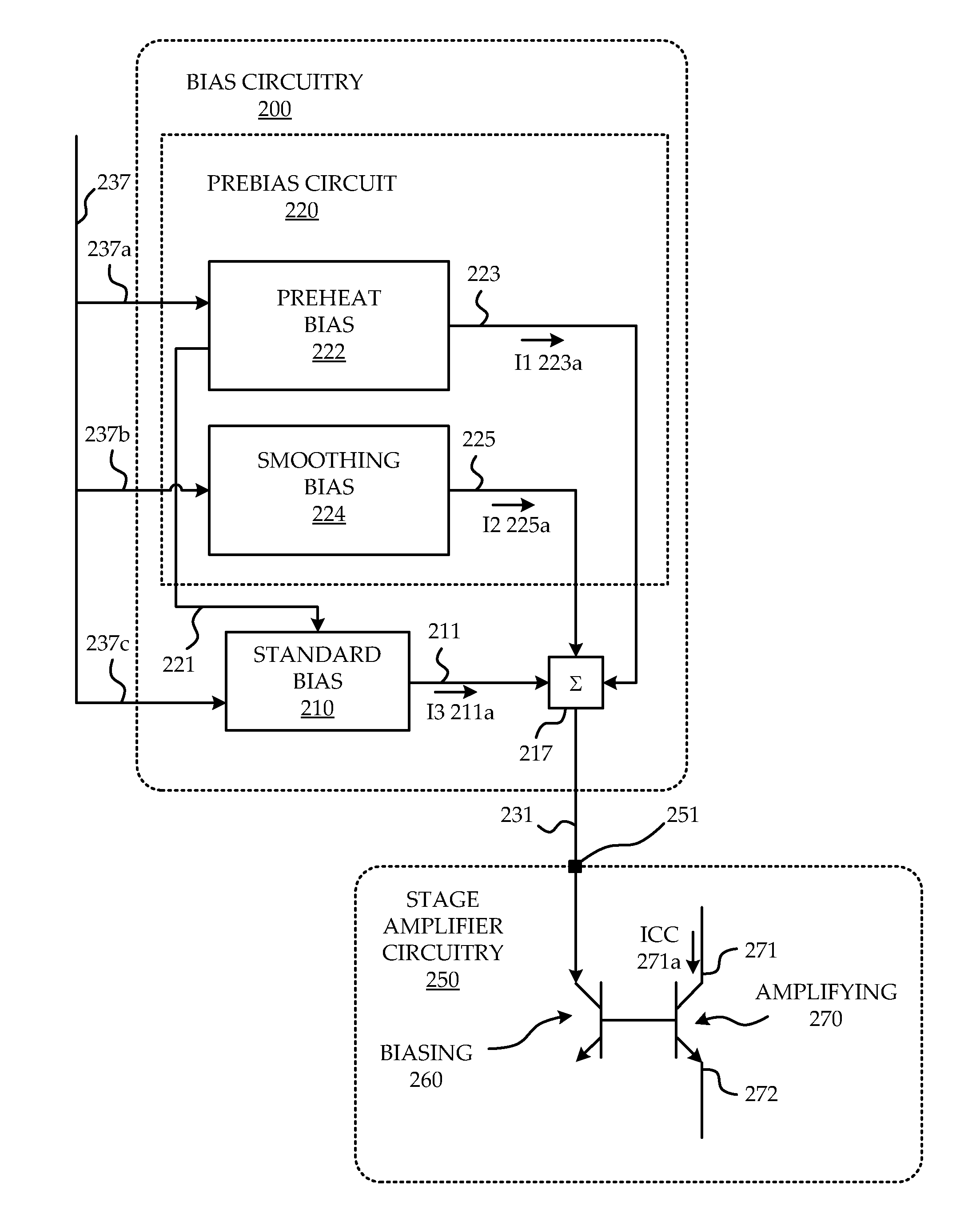
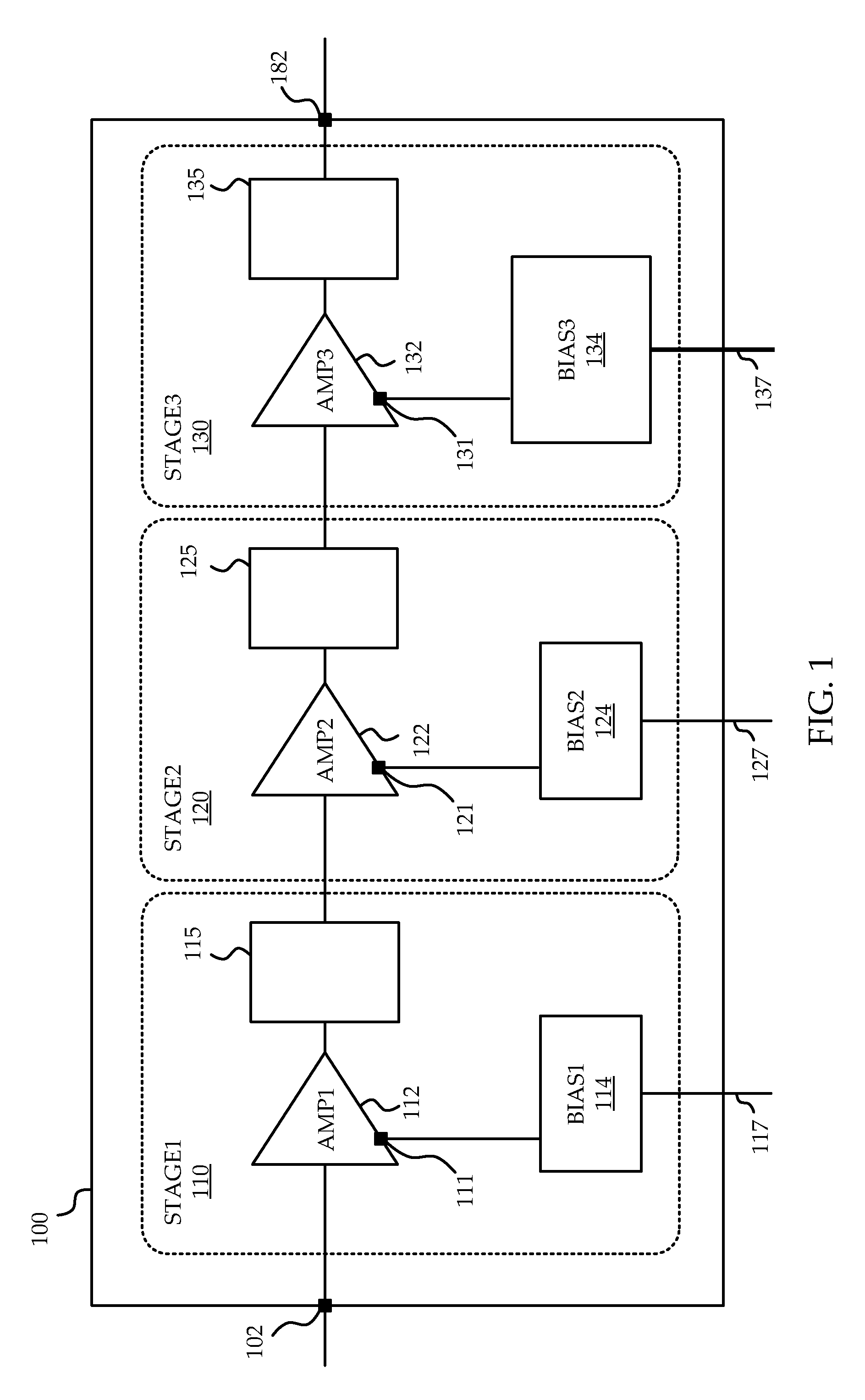
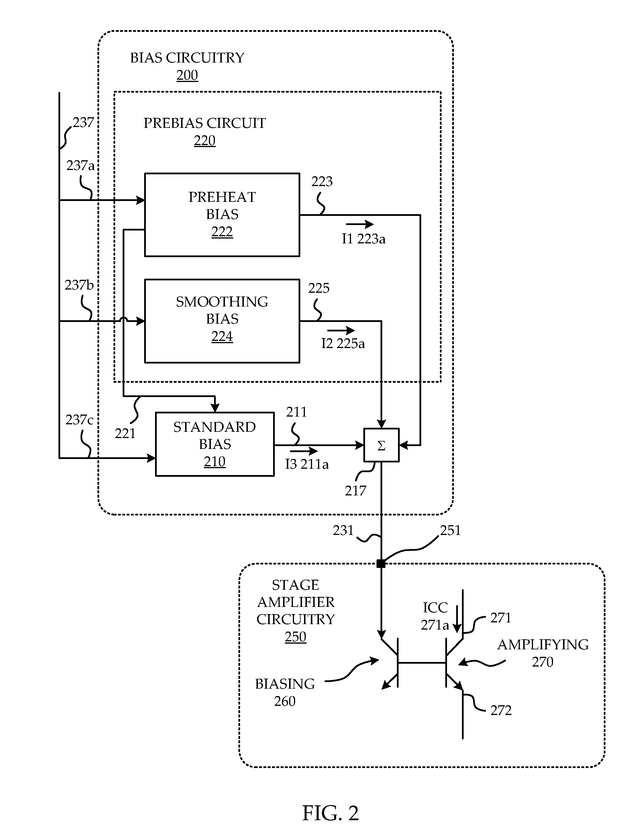
"The invention provides a method and circuit for biasing a power amplifier in RF communication. The method involves generating a high amplitude pulse bias signal and providing it to the amplifier circuit before receiving the RF signal data to be amplified. This preheat bias signal helps to bring the amplifier circuit to a steady-state level of operation. The high amplitude pulse bias signal can be generated based on an anticipatory notification of the RF signal data or a controller's control signal. The invention also provides a smoothing bias circuit that generates a smoothing bias signal to compensate for transience in the current passing through the amplifier. The combined bias signal can be generated using a first combiner or a second combiner. The technical effect of the invention is to improve the stability and efficiency of the power amplifier in RF communication."

Problems solved by technology

As such, changes in the operating conditions of the PA can lead to unwanted changes in the gain or phase response of the PA.
Transitioning from an idle state to a full-on state can create a host of various, and possibly interdependent or causally related physical changes which lead to unwanted changes in the gain or phase response of the PA during the transition period.
Although the speed-up capacitor can improve the time response of the PA, as a passive mechanism it cannot provide the additional forward current until the RF input signal itself arrives.
Consequently, the beginning of the RF signal data will suffer from some amount of dynamic EVM and the additional current may not be sufficient to bring the PA into a thermally stable state at a desired rate.
The external passive networks according to the known solutions possess various packaging and performance compromises.
External RC circuits applied to the first and / or second stage can result in reduced output power due to headroom issues of those RC circuits, and result in the addition of further components to the packaging.
Waiting for all of the stages to become thermally stable, although avoiding dynamic EVM, introduces undesirable delay.

Method used


Image

  • System and method of prebias for rapid power amplifier response correction
  • System and method of prebias for rapid power amplifier response correction
  • System and method of prebias for rapid power amplifier response correction

Examples


Embodiment Construction

[0037]The embodiments described below illustrate features of the invention in the context of an Integrated Chip (IC) power amplifier. It is to be understood that the invention applies to a power amplifier of any type, including among others, a power amplifier which is Bipolar based, tube based, or any combination thereof, as long as the power amplifier utilizes biasing voltage or current signals to set the gain or phase response of its amplification, and would benefit from compensation to minimize distortion due to changing gain or phase response during the arrival of the input signal.

[0038]The invention described herein below mitigates the aforementioned drawbacks of known systems by limiting the need for off-chip passive components, reducing the time necessary to achieve steady state gain and phase response, improving dynamic EVM performance of PAs, reducing fine tuning and optimization in the prototype phase, and compensating for secondary thermal time constants associated with I...


PUM


Abstract

A system and method are provided for reducing dynamic EVM of an integrated circuit power amplifier (PA) used for RF communication. In a multistage PA, the largest amplification stage is biased with a high amplitude current pulse upon receipt of a Tx enable, before receipt of the RF signal data burst. The high amplitude current pulse causes a large portion of the total ICQ budget of the multistage PA to pass through the largest amplification stage causing the entire integrated circuit to rapidly approach steady-state operating conditions. A smoothing bias current is applied to the largest amplification stage after the pulse decays to compensate for transient bias current levels while standard bias circuitry is still approaching steady-state temperature.

Description

FIELD OF THE INVENTION[0001]The invention relates to power amplifiers (PA), and more particularly to the correction of the gain and phase response of the PA under changing operating conditions.BACKGROUND OF THE INVENTION[0002]Correction of the gain and phase response of a power amplifier used to amplify an RF signal transmitted by an RF transmitter (or RF transceiver) can greatly improve the quality of the RF signal, and hence the performance of the RF transmitter. Under steady-state operating conditions, an amplifier and its associated circuitry generally perform in an expected, well behaved, and steady manner. Most PAs are designed and tuned so that, if a specific gain bias current (or voltage) is applied to it, it amplifies a signal with a predetermined and steady gain and phase response. This steady gain and phase response holds in general if the PA is operating under steady-state operating conditions, but does not necessarily apply under changing operating conditions.[0003]Chan...

Claims


Application Information

Patent Timeline
Patent Type & Authority Patents(United States)
IPC IPC(8): H04B1/04
CPCH03G3/3047H03F1/302H03F3/211H03F3/245H03F2200/447H03F2200/18H03F2200/408
Inventor DOHERTY, MARKLAM, LUI RAYHUANG, CHEN-WEN PAULQUAGLIETTA, ANTHONY
Owner SIGE SEMICON
Learn More