Yarn brake for a two-for-one twisting spindle

a two-for-one twisting spindle and yarn brake technology, which is applied in the direction of yarn, piercing arrangement, textiles and paper, etc., can solve the problems of yarn tensioning during the twisting process, inability to be corrected, and relatively low achievable braking force in each case, so as to avoid yarn tensioning. increase

Active Publication Date: 2012-09-04
SAURER TECH GMBH & CO KG
View PDF13 Cites 0 Cited by
  • Summary
  • Abstract
  • Description
  • Claims
  • Application Information

AI Technical Summary

Benefits of technology

[0008]In view of the aforementioned prior art, it is an object of the present invention to develop a yarn brake for a two-for-one twisting spindle, which is configured to substantially avoid yarn tension increases, which could lead to a yarn break.
[0011]An advantageous embodiment of the invention provides that the angle, which is adjusted upon the occurrence of yarn anomalies between the center longitudinal axis of the upper piston and the center longitudinal axis of the housing of the yarn brake, is up to 10°. By means of such a relatively small tilting angle, on the one hand, the structural outlay in the region of the yarn brake can be minimized, but it can nevertheless be ensured that the occurrence of high yarn tensions is avoided when, for example, knots, thick locations or lumps of dust run over the upper brake face.
[0013]A configuration of this type, on the one hand, ensures clean guidance of the upper piston in the housing of the yarn brake during “normal” twisting operation and, on the other hand, if necessary allows an immediate, reliable moving away of the upper brake face.
[0014]At least the disc-shaped lower guide lug has a convexly curved, peripheral guide face in an advantageous configuration. A convexly curved guide face of this type, on the one hand, favors the tilting capacity of the piston and, on the other hand, reliably prevents the piston being able to be jammed in the housing. Overall, a convexly curved, peripheral guide face, when necessary, has a positive effect on the functioning of the yarn brake.
[0015]It is provided in an advantageous configuration that the upper piston is loaded by two spring elements arranged one behind the other, which in each case have different spring characteristics and the pretensioning of which can be adjusted in a defined manner by a rotatably mounted abutment device. The abutment device in this case has helically arranged latching positions, which can be easily engaged by corresponding rotation of the abutment device in the housing of the yarn brake.
[0016]The lower brake face, on which the brake element is pressed, may be integrated in a lower piston, which, loaded by a spring element, is positioned in a working position and can be pneumatically lowered into a threading position to yarn a new yarn. A configuration of this type considerably facilitates the threading of a new yarn.

Problems solved by technology

The drawback in brake cartridges of this type is, however, that the pretensioning of the yarn during the twisting process is only predetermined by the spring force of the spring element of the brake cartridge and, at least during the twisting process, cannot be corrected.
In brake devices configured in this manner, the achievable braking force is relatively low in each case, however.
Brake devices of this type not only require a relatively large installation space, but are extremely disadvantageous with regard to threading a new yarn.
The drawback in this type of yarn brake is, however, that the spring-loaded piston, which has the upper brake face, slides virtually without play in an axial guide of the yarn brake housing.
In other words, the upper brake face cannot move away laterally, which leads to the fact that yarn anomalies such as knots, thick locations, lumps of dust, etc., lead to strong yarn tension increases through to yarn breaks.

Method used


Image

  • Yarn brake for a two-for-one twisting spindle
  • Yarn brake for a two-for-one twisting spindle
  • Yarn brake for a two-for-one twisting spindle

Examples


Embodiment Construction

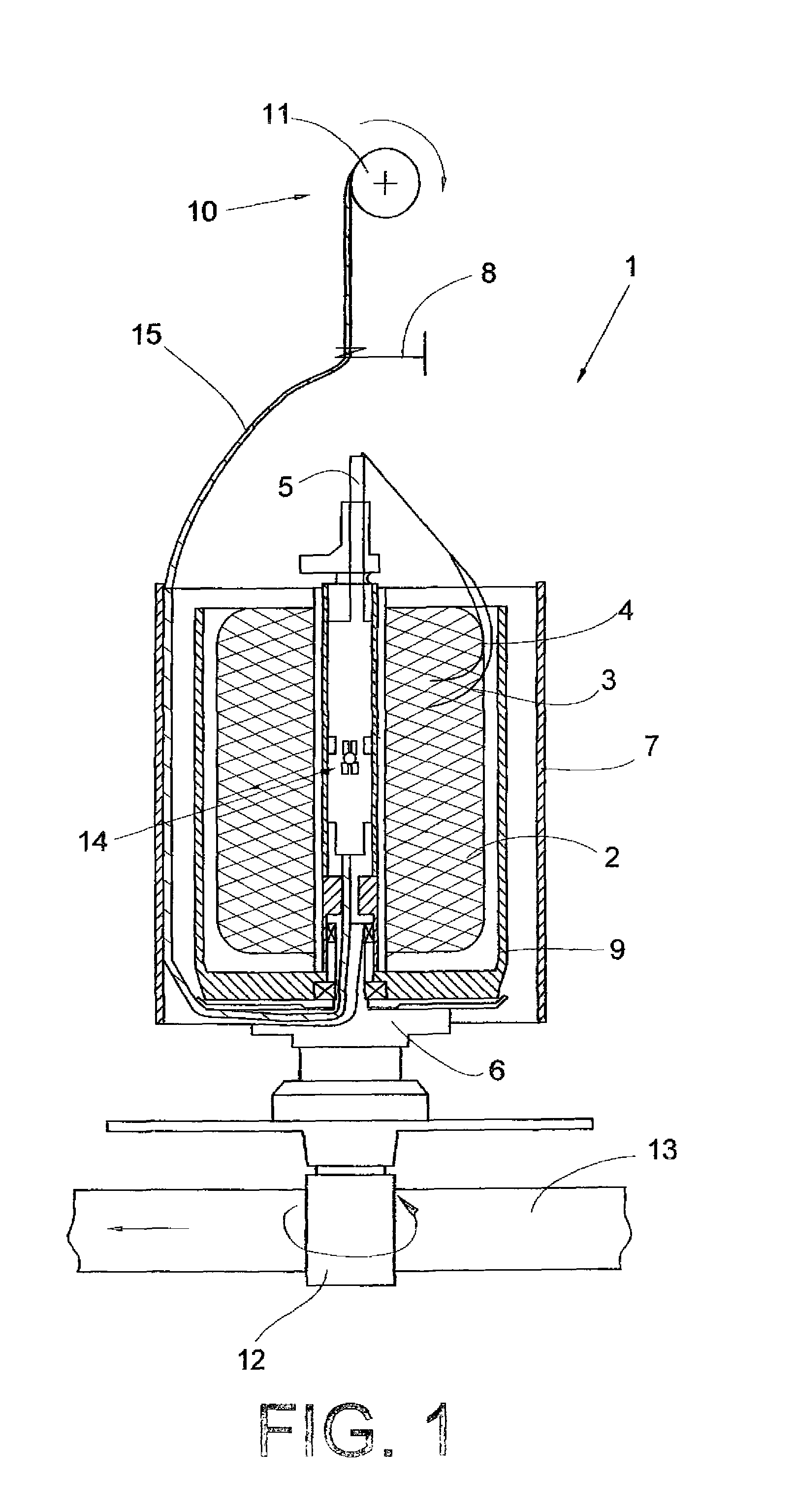
[0030]FIG. 1 schematically shows, partially in section, a two-for-one twisting spindle designated as a whole by the reference numeral 1. A yarn or a plurality of yarns, are provided with a twist by a two-for-one twisting spindle 1 of this type. This provision of a twist is used to increase the quality of the yarn / yarns, for example with regard to the tearing strength and therefore improved further processability in subsequent processes, such as, for example, weaving, knitting, tufting and the like.

[0031]The actual double twist process in this case proceeds as follows. As shown in the embodiment of FIG. 1, yarns 3 and 4 are unwound, for example, from a supply bobbin 2, which is mounted in a stationary protection pot 9 and drawn from above into the hollow axle 5 of the two-for-one twisting spindle 1. When crossing the hollow axle 5, the yarns 3 and 4 are twisted by a rotatably mounted spindle part 6, which is arranged below the protection pot 9, deflected in an L-shaped manner and arr...


PUM

PropertyMeasurementUnit
angleaaaaaaaaaa
braking forceaaaaaaaaaa
diameteraaaaaaaaaa

Abstract

A yarn brake for a two-for-one twisting spindle has a brake element mounted in the region of a hollow axle of the spindle between an upper and a lower brake face, the braking force being predeterminable in a defined manner by means of the pretensioning of at least one spring element, which acts on an axially displaceably mounted upper piston, in which the upper brake face is integrated, and the yarn brake being pneumatically releasable to introduce a yarn. The upper piston (27) receiving the upper brake face (28) is configured in such a way and guided with play (S) within a housing (16) of the yarn brake (14) in such a way that it can move aside if necessary into a position (I), in which its center longitudinal axis (37) forms an angle (α) with the center longitudinal axis (38) of the housing (16).

Description

CROSS-REFERENCE TO RELATED APPLICATIONS[0001]This application claims the benefit of German patent application 10 2009 058 979.1, filed Dec. 18, 2009, herein incorporated by reference.FIELD OF THE INVENTION[0002]The invention relates to a yarn brake for a two-for-one twisting spindle.BACKGROUND OF THE INVENTION[0003]Yarn brakes for two-for-one twisting spindles have been known for a long time in various configurations and are described, sometimes in detail, in numerous patents. Yarn brakes of this type are, in particular, used in two-for-one twisting processes and ensure that the yarn receives a specific pretensioning during the twisting process.[0004]A two-for-one twisting spindle with a yarn brake, which is configured as a brake cartridge, is known, for example, from DE 31 39 236 C2. In yarn brakes of this type configured as brake cartridges, two cylinders pressed apart from one another by a spring element and slidable telescopically relative to one another are supported by their s...

Claims


Application Information

Patent Timeline
Patent Type & Authority Patents(United States)
IPC IPC(8): D01H15/007
CPCD01H13/106
Inventor BECKERS, JOACHIMBECKMANN, MARKUSFILZ, INGOFINK, HEINZSCHNITZLER, JURGEN
Owner SAURER TECH GMBH & CO KG
Why Eureka
Try Eureka