
Electroactive polymer transducers

a polymer film and transducer technology, applied in the direction of diagnostic recording/measuring, fixed capacitor details, fixed capacitors, etc., can solve the problems of dielectric elastomer transducers being particularly damaged by air partial discharges, shortening the life of transducers, etc., to reduce the high concentration of electrical stress gradients, suppress or minimize partial discharges, the effect of minimizing the corona

Active Publication Date: 2012-08-21
BAYER MATERIALSCIENCE AG
View PDF2 Cites 35 Cited by
  • Summary
  • Abstract
  • Description
  • Claims
  • Application Information

AI Technical Summary

Benefits of technology

The application of a partial discharge suppressant coating effectively minimizes partial discharge and corona, extending the lifespan of dielectric elastomer transducers by reducing electrical stress and degradation.

Problems solved by technology

Like any high voltage device, EAP transducers are susceptible to partial discharge.
Partial discharges through air are particularly damaging to dielectric elastomer transducers.
These reactive species, in combination with the high temperatures present within the electrical arc, erode the electrode and dielectric materials and can shorten the life span of a transducer.

Method used


Image

  • Electroactive polymer transducers
  • Electroactive polymer transducers
  • Electroactive polymer transducers

Examples


Embodiment Construction

[0023]Before describing particular embodiments of the materials, devices and systems of the present invention, a discussion of compliant electroactive capacitive structures and their material properties and performance characteristics is provided.

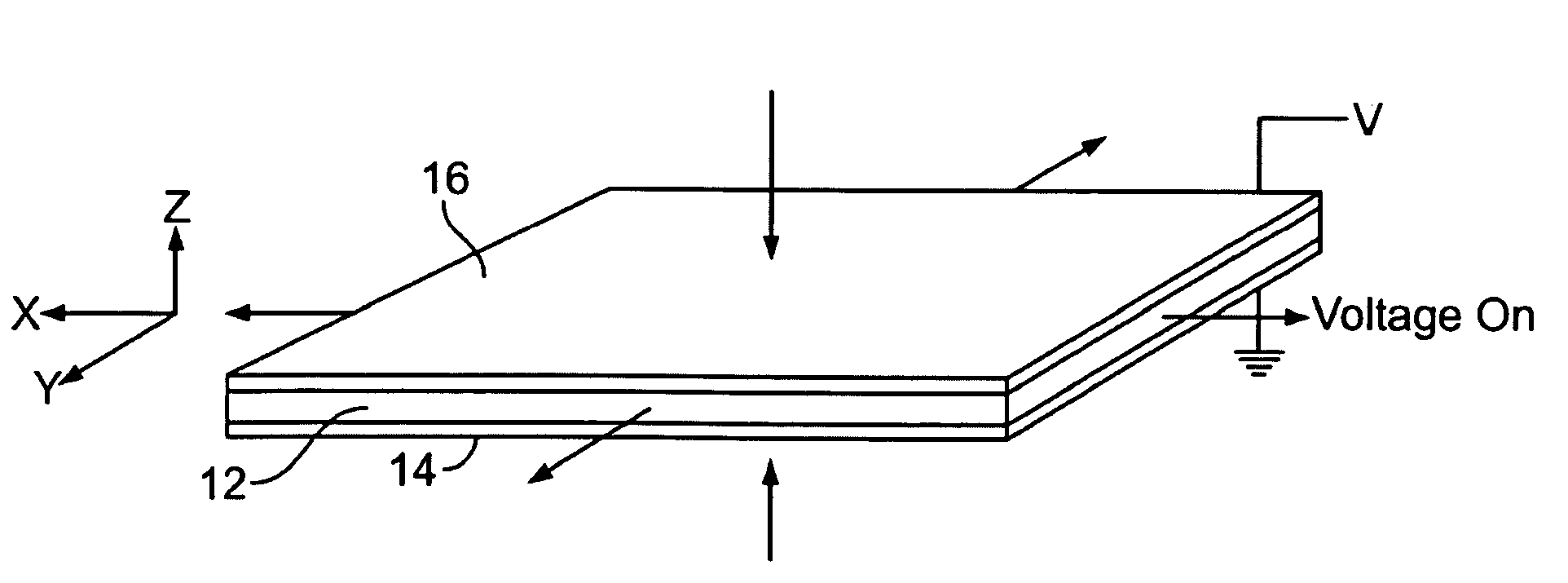
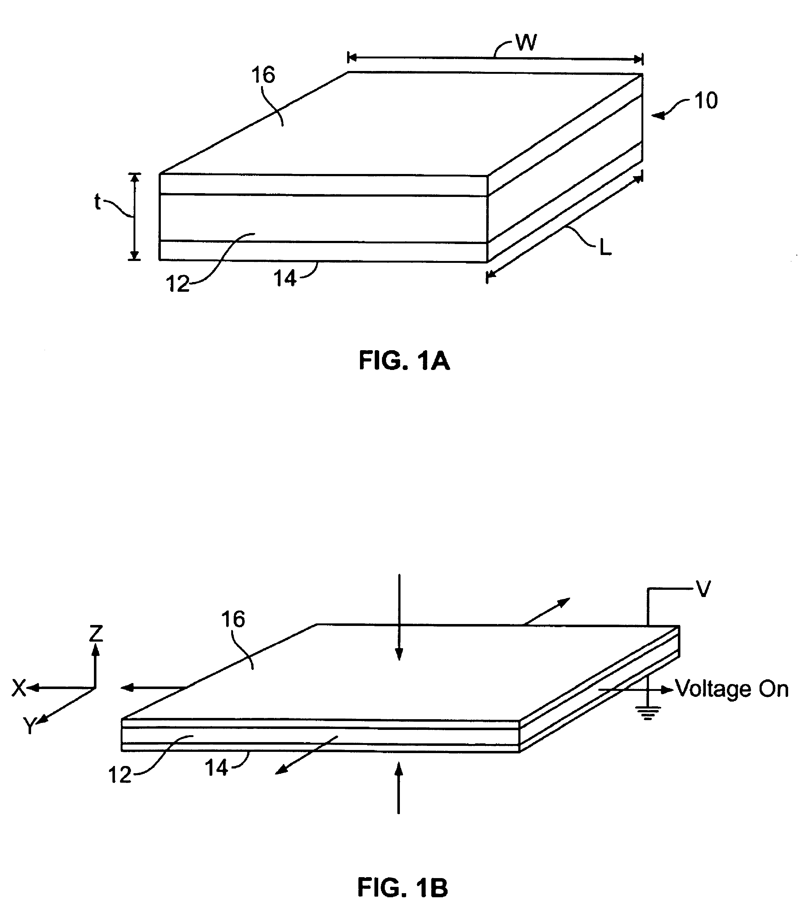
[0024]FIGS. 1A and 1B illustrate a capacitive structure in the form of an electroactive film or membrane 10. A thin elastomeric dielectric film or layer 12 is sandwiched between compliant or stretchable electrode plates or layers 14 and 16, thereby forming a capacitive structure or film. The length “l” and width “w” of the dielectric layer, as well as that of the composite structure, are much greater than its thickness “t”. Typically, the dielectric layer has a thickness in range from about 10 μm to about 100 μm, with the total thickness of the structure in the range from about 25 μm to about 10 cm. Additionally, it is desirable if possible to select the elastic modulus, thickness, and / or the microgeometry of electrodes 14, 16 such that the...


PUM

PropertyMeasurementUnit
elastic modulusaaaaaaaaaa
total thicknessaaaaaaaaaa

Abstract

Dielectric elastomer or electroactive polymer film transducers configured to minimize high electrical field gradients that can lead to partial discharge and corona.

Description

CROSS-REFERENCE TO RELATED APPLICATIONS[0001]The present application is a continuation-in-part of U.S. patent application Ser. No. 11 / 956,269, filed on Dec. 13, 2007, the content of which is incorporated herein by reference in its entiretyFIELD OF THE INVENTION[0002]The present invention relates to dielectric elastomer or electroactive polymer film transducers and optimizing their performance by minimizing high electrical field gradients that can lead to partial discharge and corona.BACKGROUND OF THE INVENTION[0003]A tremendous variety of devices used today rely on actuators of one sort or another to convert electrical energy to mechanical energy. Conversely, many power generation applications operate by converting mechanical action into electrical energy. Employed to harvest mechanical energy in this fashion, the same type of actuator may be referred to as a generator. Likewise, when the structure is employed to convert physical stimulus such as vibration or pressure into an electr...

Claims


Application Information

Patent Timeline
Patent Type & Authority Patents(United States)
IPC IPC(8): H01G4/018H10N30/00H10N30/098H10N30/20H10N30/30H10N30/857
CPCH01L41/0986H01L41/0533H01L41/45Y10T29/49007H10N30/883H10N30/206H10N30/098A61B5/00H10N30/00
Inventor BIGGS, SILMON JAMESJOHNSON, EDWARD F.RUSSELL, GORDONWHITE, III, LUTHER LAWFORD
Owner BAYER MATERIALSCIENCE AG
Learn More