
Volatile chemical substance catching device and electronic apparatus

a technology of electronic equipment and volatile chemical substances, which is applied in the direction of optics, instruments, electrographic processes, etc., can solve the problems of forming equipment such as copiers and printers not only emitting vocs, but also having a problem with peculiar odors, secondary negative effects,

Active Publication Date: 2012-08-07
SHARP KK
View PDF13 Cites 5 Cited by
  • Summary
  • Abstract
  • Description
  • Claims
  • Application Information

AI Technical Summary

Benefits of technology

The present technology aims to provide a device and an electronic apparatus that can catch volatile chemical substances, such as VOCs and odors, over a long period of time without experiencing performance deterioration. The device includes a volatile chemical substance catching section that generates an electric field in the atmosphere to attract and catch the volatile chemical substances. The caught substances can be easily removed for repeated use. The technology also includes a connector for supplying voltage to the catching section. Overall, the technology provides a more efficient and durable solution for capturing volatile chemicals.

Problems solved by technology

In recent years, VOCs have drawn attention as substances that cause allergy symptoms or sick building syndrome, which develops into health hazards such as headaches and dizziness.
Furthermore, among these electronic apparatuses, image forming apparatuses such as copiers and printers not only emit VOCs, but also have a problem with peculiar odors that are generated from heated sheets of paper or heated toner.
First, in the case of use of a filter to catch volatile chemical substances such as VOCs and odors, there naturally occurs aged deterioration in performance. In order to overcome such aged deterioration in performance, the honeycomb structure is made finer to increase in area of contact with air currents. However, there is a trade-off, i.e., a hindrance to passage of heat out of the image forming apparatus, which causes a rise in temperature in the image forming apparatus, and such a rise in temperature consequently brings about a secondary negative effect.
Second, in the case of use of a needle electrode as a negative ion generating device, foreign matter (e.g., Si-based material) adheres to the needlepoint to cause discharging deficiency, thus causing a decrease in emissions of negative ions. Further, since the needlepoint is blunted over time by application of a high voltage, deterioration in performance cannot be avoided.

Method used


Image

  • Volatile chemical substance catching device and electronic apparatus
  • Volatile chemical substance catching device and electronic apparatus
  • Volatile chemical substance catching device and electronic apparatus

Examples


embodiment 1

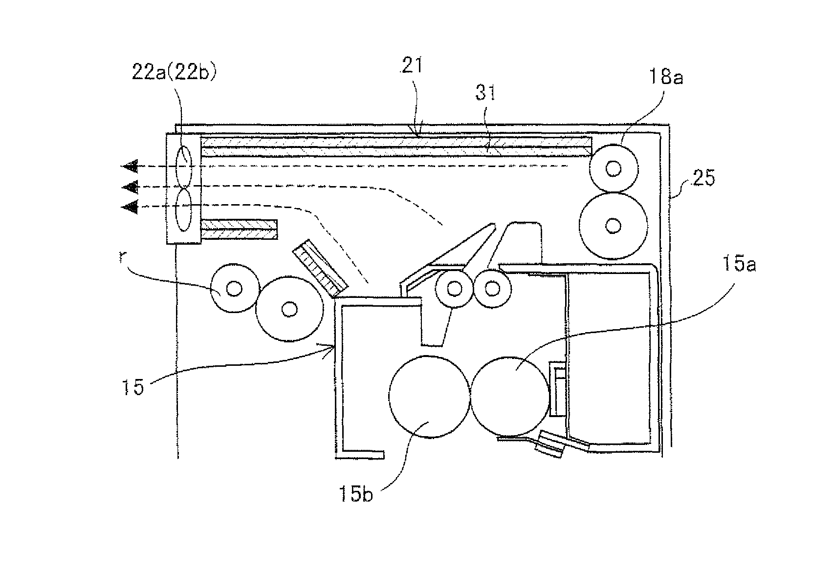
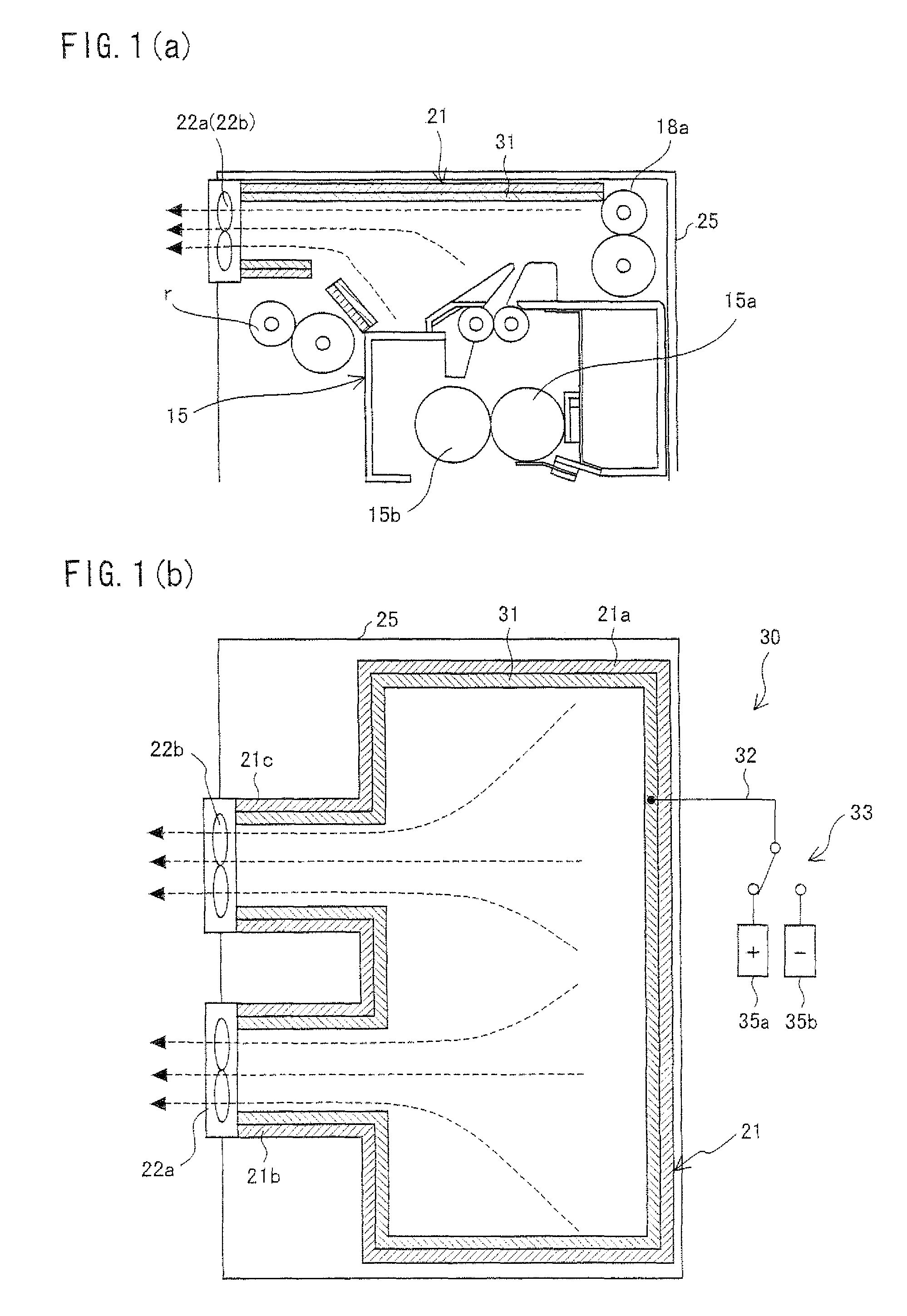
[0026]Embodiment 1 of the present technology is described below with reference to the attached drawings. It should be noted that the present embodiment explains a case where an image forming apparatus of the present technology is applied to a color multifunction apparatus 100.

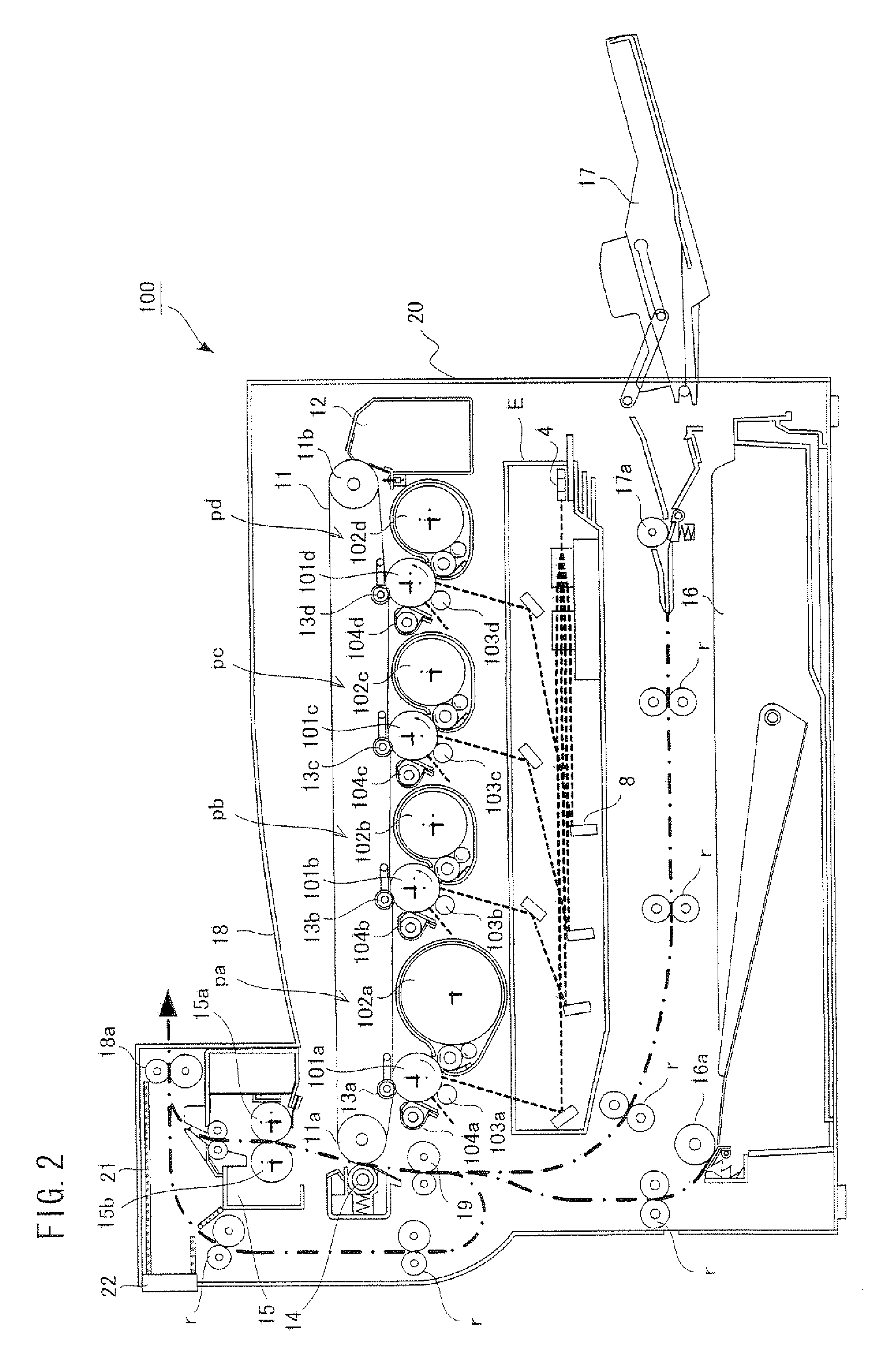
[0027]FIG. 2, showing Embodiment 1, is a longitudinal sectional view schematically illustrating an arrangement of the color multifunction printer 100.

[0028]The color multifunction printer 100 is an electrophotographic image forming apparatus that forms a multicolor or monochrome image on a sheet (recording material, recording sheet of paper) in accordance with print job data inputted from a personal computer or the like (not illustrated).

[0029]As illustrated in FIG. 2, the color multifunction printer 100 has an image forming section that forms an image on a sheet. The image forming section includes: an optical unit E; four visible-image forming units pa, pb, pc, and pd; an intermediate transfer belt 11; a secon...

embodiment 2

[0067]Embodiment 2 of the present technology is described with reference to the attached drawings. A color multifunction printer of the present embodiment differs from the aforementioned color multifunction printer 100 of Embodiment 1 in that the color multifunction printer of the present embodiment has auxiliary electric-field generating and catching members 34a and 34b provided in the exhaust duct 21. The auxiliary electric-field generating and catching members 34a and 34b serve as auxiliary members for the electric-field generating and catching member 31 of the volatile chemical substance catching device 30.

[0068]Except for the provision of the auxiliary electric-field generating and catching members 34a and 34b, the multifunction printer of the present embodiment is identical to the aforementioned color multifunction printer 100 of Embodiment 1. Therefore, components identical to those of Embodiment 1 are not described here.

[0069]FIG. 3(a) is a longitudinal sectional view of the...

embodiment 3

[0075]Embodiment 3 of the present technology is described below with reference to the attached drawings. A color multifunction printer of the present embodiment differs from the aforementioned color multifunction printer 100 of Embodiment 1 in that the color multifunction printer of the present embodiment has VOC gas treating active carbon honeycomb filters 36a and 36b provided in the exhaust duct 21.

[0076]Except for the provision of the VOC gas treating active carbon honeycomb filters 36a and 36b, the multifunction printer of the present embodiment is identical to the aforementioned color multifunction printer 100 of Embodiment 1. Therefore, components identical to those of Embodiment 1 are not described here.

[0077]FIG. 4(a) is a longitudinal sectional view of the fixing unit 15 of the present embodiment and the vicinity of an area above the fixing unit 15, and FIG. 4(b) is a transverse sectional view of the area above the fixing unit 15 of the present embodiment. It should be note...


PUM


Abstract

A color multifunction printer of the present invention includes a volatile chemical substance catching device, provided in an exhaust duct provided above a fixing unit, which generates an electric field in an atmosphere with use of an electric-field generating and catching member, which attracts volatile chemical substances contained in the atmosphere to a surface of the electric-field generating and catching member by the action of the electric field, and which catches the volatile chemical substances. This makes it possible to realize a volatile chemical substance catching device and an electronic apparatus that hardly suffer from aged deterioration in performance and can catch volatile chemical compounds such as VOCs and odors over a long period of time.

Description

[0001]This Nonprovisional application claims priority under 35 U.S.C. §119(a) on Patent Application No. 2008-136920 filed in Japan on May 26, 2008, the entire contents of which are hereby incorporated by reference.TECHNICAL FIELD[0002]The present technology relates to a volatile chemical substance catching device and an electronic apparatus (such as a personal computer, a copier, or a printer) for catching volatile chemical substances (chemical emissions) such as odors and VOCs (volatile organic compounds).BACKGROUND ART[0003]In recent years, VOCs have drawn attention as substances that cause allergy symptoms or sick building syndrome, which develops into health hazards such as headaches and dizziness. The VOCs are known to be emitted from electronic apparatuses such as personal computers, copiers, and printers. Furthermore, among these electronic apparatuses, image forming apparatuses such as copiers and printers not only emit VOCs, but also have a problem with peculiar odors that ...

Claims


Application Information

Patent Timeline
Patent Type & Authority Patents(United States)
IPC IPC(8): G03G21/20
CPCG03G21/206G03G2221/1645
Inventor DOSHODA, HIROSHIKAGAWA, TOSHIAKI
Owner SHARP KK
Learn More