
Boot for constant-velocity universal joint and fixing structure for the same

a technology of constant velocity and universal joints, which is applied in the direction of mechanical equipment, couplings, transportation and packaging, etc., can solve the problems of degrading the degree of freedom in designing and manufacturing conventional boots, and affecting the design and manufacturing of conventional boots. , to achieve the effect of preventing the degree of design freedom from degrading and preventing the weight from increasing

Inactive Publication Date: 2008-10-23
TOYODA GOSEI CO LTD +1
View PDF11 Cites 2 Cited by
  • Summary
  • Abstract
  • Description
  • Claims
  • Application Information

AI Technical Summary

Benefits of technology

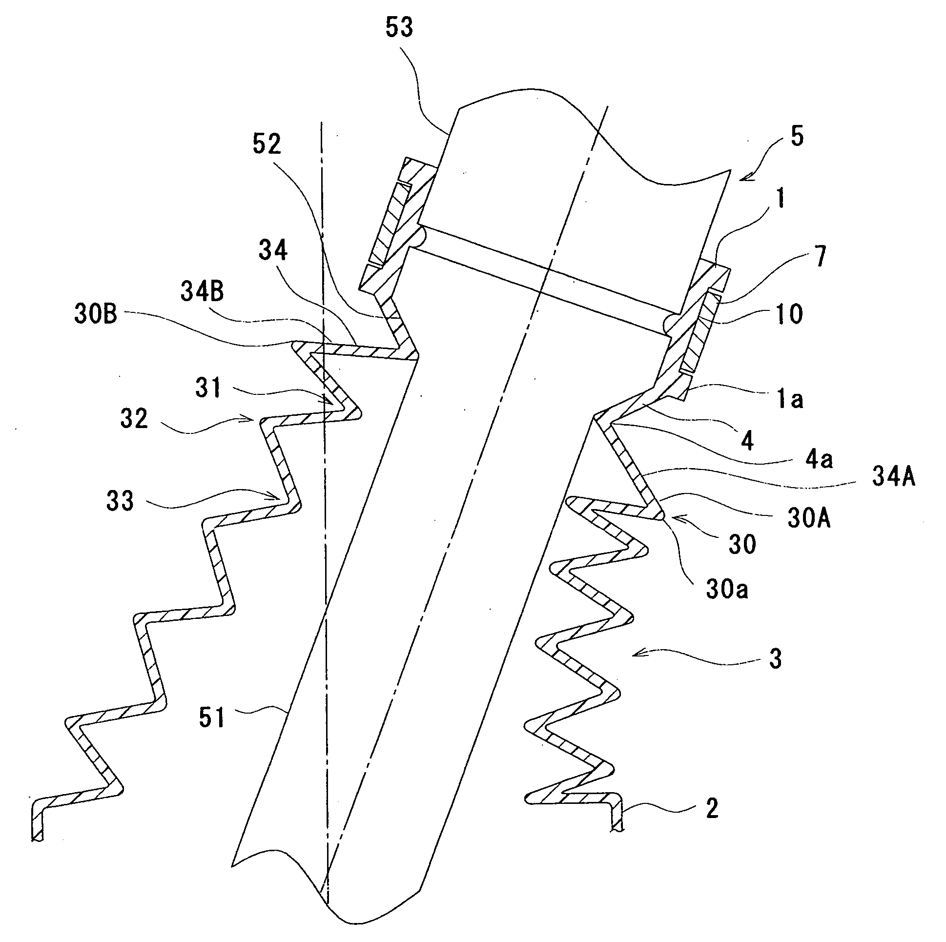
[0028]The present boot for constant-velocity universal joint comprises the tapered wall portion or the vertical wall portion, which is disposed between the minor-diameter cylindrical portion and the bellows. Accordingly, even when the bellow's rising wall deforms upon putting the present boot in service, the deforming rising wall brings the tapered wall portion or vertical wall portion into contact, close contact or pressure contact with the tapered surface or vertical surface of the shaft, and thereby the tapered wall portion or vertical wall portion can shut off stress, which occurs resulting from the deforming of the rising wall, from transmitting toward the minor-diameter cylindrical portion. Consequently, even when the present boot is curved or bent greatly and then rotates so that the rising wall of the bellows has deformed greatly, the tapered wall portion or vertical wall portion can keep stress, which arises from the deforming of the rising wall, from transmitting to the minor-diameter cylindrical portion. Therefore, the tapered wall portion or vertical wall portion can inhibit the one of the opposite ends of the minor-diameter cylindrical portion, which adjoins the bellows, from sinking downward and floating upward. All in all, the tapered wall portion or vertical wall portion can prevent grease leakage, which results from the above-described pumping action, from occurring.
[0029]Moreover, in the present boot for constant-velocity universal joint, the tapered wall portion or vertical wall portion contacts, close contacts or pressure contacts with the tapered surface or vertical surface of the shaft as described above, thereby shutting off stress, which results from the deforming of the rising wall, from transmitting toward the minor-diameter cylindrical portion. In other words, it is not the case at all that heightening the rigidity of the tapered wall portion or vertical wall portion essentially results in shutting off stress transmission. Accordingly, unlike the above-described second conventional boot for constant-velocity universal joint in which stress transmission is shut off by heightening the rigidity of the retaining cylindrical portion, it is not necessary to make the retaining cylindrical portion longer or to make it thicker. Consequently, the present boot hardly suffers from such problems that its weight has increased, and that the degree of freedom in designing and manufacturing has degraded.
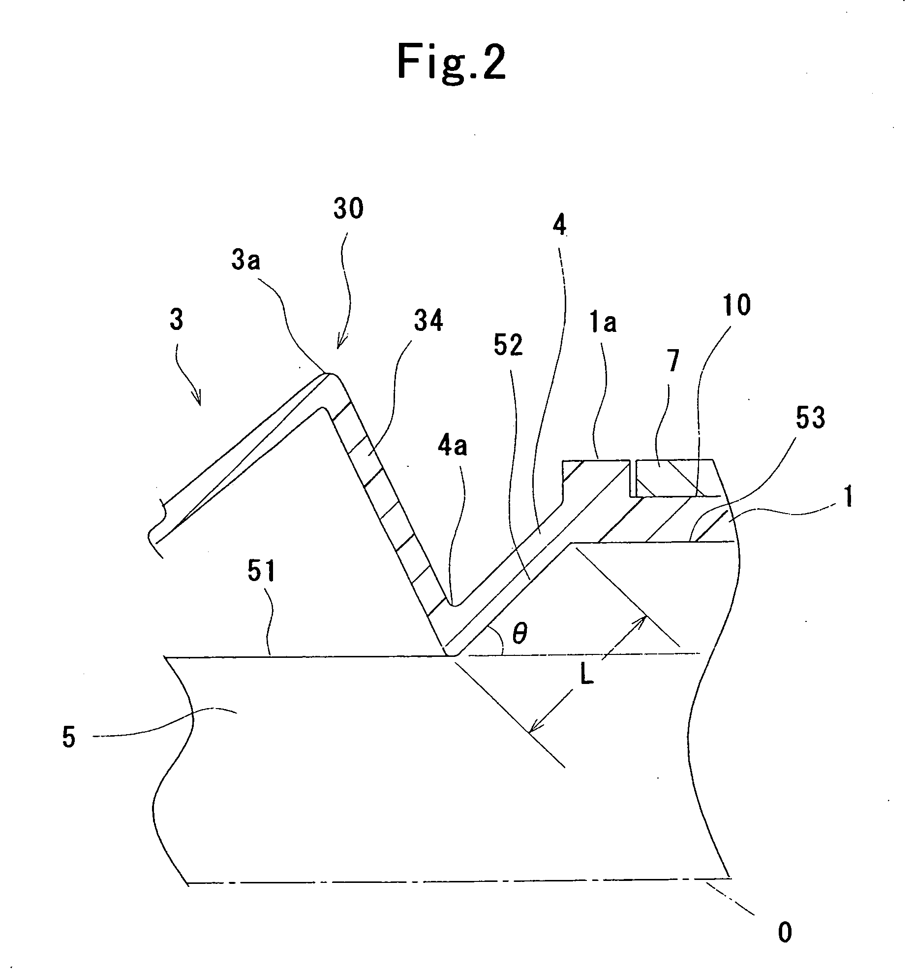
[0032]Moreover, the tapered wall portion can preferably exhibit the angle “θ” and a length “L” that are suitable for effectively inhibiting stress from transmitting from the rising wall to the minor-diameter cylindrical portion. Note herein that the length “L” of the tapered wall portion designates an inside oblique dimension that extends from one of the opposite ends of the minor-diameter cylindrical portion, which faces the bellows, to the rising wall's inside bottom end, which adjoins the tapered wall portion, obliquely.
[0041]Therefore, the present boot for constant-velocity universal joint and the present fixing structure for boot for constant-velocity universal joint can keep grease from leaking while not only inhibiting their weight from increasing but also prohibiting their degree of designing freedom from degrading.

Problems solved by technology

Consequently, the conventional boot might have been associated with the following problems.
As a result, there might be such a fear that grease leakage occurs.
However, the lengthened or thickened retaining cylindrical portion has resulted in the weight increment of the conventional boot, or in the degrading degree of freedom in designing and manufacturing the conventional boot.

Method used


Image

  • Boot for constant-velocity universal joint and fixing structure for the same
  • Boot for constant-velocity universal joint and fixing structure for the same
  • Boot for constant-velocity universal joint and fixing structure for the same

Examples


examples

[0051]Hereinafter, specific examples of a boot for constant-velocity universal joint according to the present invention and a fixing structure for the same will be described in detail while referring to the drawings.

first embodiment

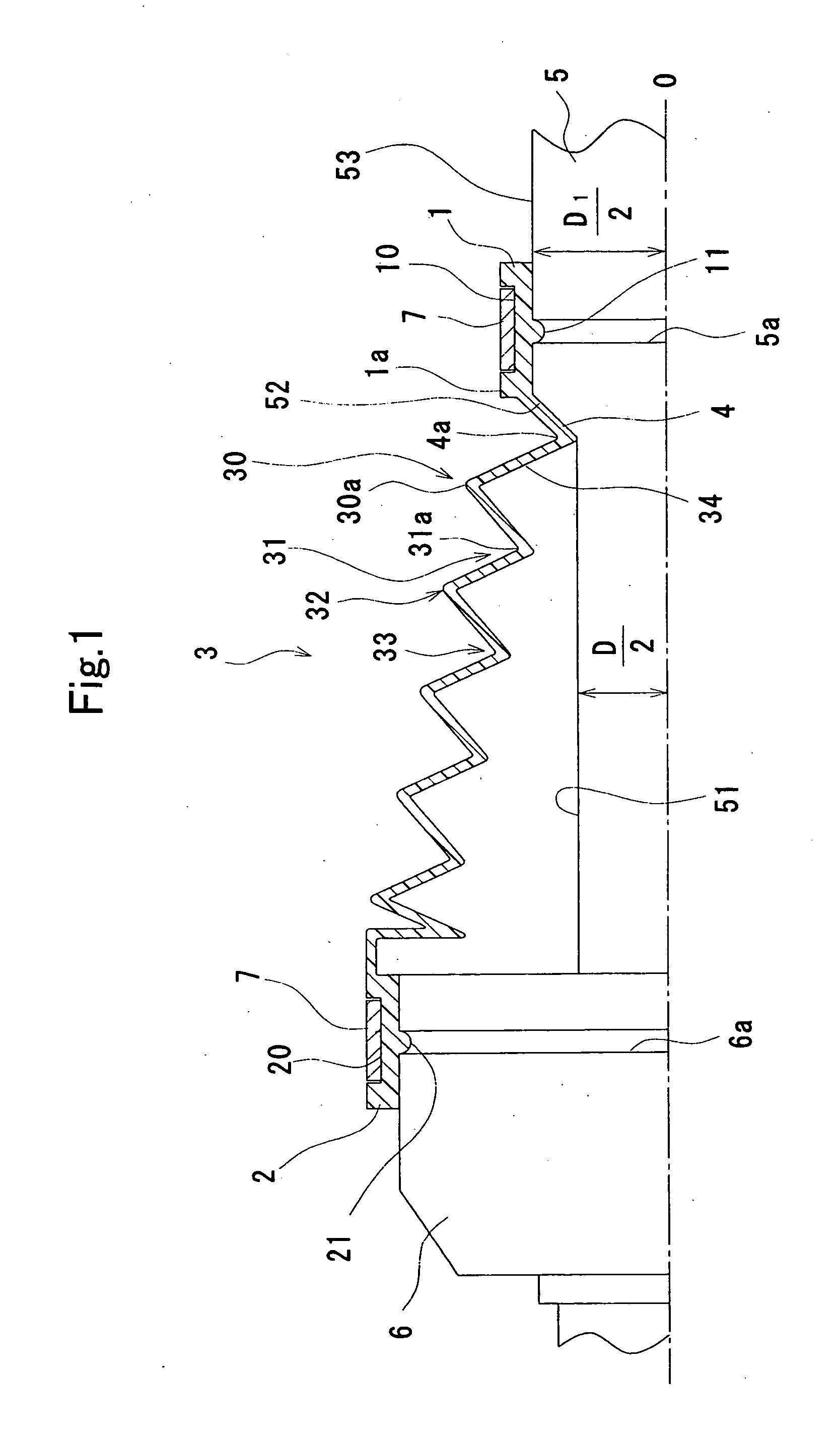
[0052]FIG. 1 illustrates a boot for constant-velocity universal joint according to First Embodiment of the present invention partially. The drawing shows how the present boot according to First Embodiment appears when it is fixed to a shaft and a joint outer race (i.e., a mating member). Moreover, the drawing is a partial vertical cross-sectional view that is taken by cutting the present boot according to First Embodiment with an imaginary plane involving its imaginary central line “O.”FIG. 2 is a partially-enlarged cross-sectional diagram for illustrating a major part of FIG. 1 in a partially-enlarged cross-sectional view. FIG. 3 is a cross-sectional diagram for illustrating how the present boot according to First Embodiment appears in service.

[0053]As illustrated in FIG. 1, the present boot according to First Embodiment comprises a minor-diameter cylindrical portion 1, a major-diameter cylindrical portion 2, a bellows 3, and a tapered wall portion 4. The major-diameter cylindrical...

second embodiment

[0076]FIG. 5 is directed to a boot according to Second Embodiment of the present invention, or a fixing structure for the same, and illustrates its major part in an enlarged cross-sectional view. As shown in the drawing, it comprise a vertical surface 54 and a vertical wall portion 8 instead of the tapered surface 52 and tapered wall portion 4 that make the present boot according to First Embodiment, or a fixing structure for the same.

[0077]Specifically, in the present boot according to Second Embodiment, or in a fixing structure for the same, the shaft 5 comprises the general surface 51, a vertical surface 54, and the major-diameter surface 53 that are disposed one after another in this order from the left to right in FIG. 5. The vertical surface 54 extends from one of the opposite ends of the general surface 51, which faces the minor-diameter cylindrical portion 1, in a diametric direction outward and perpendicularly to the general surface 51, and exhibits a maximum outside diamet...


PUM


Abstract

A boot for constant-velocity universal joint is retained to a shaft, which has a general surface, a tapered surface, or a vertical surface instead of the tapered surface, and a major-diameter surface that are disposed one after another in this order and coaxially. The boot includes a minor-diameter cylindrical portion, a major-diameter cylindrical portion, a tapered wall portion, or a vertical wall portion instead of the tapered wall portion, and a bellows. The minor-diameter cylindrical portion is retained to the major-diameter surface of the shaft. The major-diameter cylindrical portion is disposed separately away from the minor-diameter cylindrical portion and coaxially therewith. The tapered wall portion is in contact with the tapered surface of the shaft. The vertical wall portion is in contact with the vertical surface of the shaft. The bellows connects the tapered wall portion or the vertical wall portion with the major-diameter cylindrical portion integrally.

Description

[0001]The present invention is based on Japanese Patent Application No. 2007-88,841, filed on Mar. 29, 2007, the entire contents of which are incorporated herein by reference.BACKGROUND OF THE INVENTION[0002]1. Field of the Invention[0003]The present invention relates to a boot for constant-velocity universal joint, and a fixing structure for the same. More particularly, it relates to a boot for constant-velocity universal joint, and a fixing structure for the same, boot which covers constant-velocity universal joint, an indispensable component part for the joint of drive shaft for front-wheel-drive vehicle, to inhibit water and dust from coming in the joint element of constant-velocity universal joint.[0004]2. Description of the Related Art[0005]Constant-velocity universal joints have been used for driving-power transmission systems for transmitting driving power from automotive engines to drive wheels, in particular, for drive shafts for front-wheel-drive vehicles. The constant-ve...

Claims


Application Information

Patent Timeline
Patent Type & Authority Applications(United States)
IPC IPC(8): F16J3/04B60B35/16
CPCF16D3/845F16J3/042
Inventor KUMAZAKI, HIROSHISUZUKI, SATOSHITAKEUCHI, OSAMU
Owner TOYODA GOSEI CO LTD
Learn More