
Reinforcing fiber base material for preforms, process for the production of laminates thereof, and so on

a technology of reinforced fiber and preforms, applied in the direction of synthetic resin layered products, chemistry apparatus and processes, transportation and packaging, etc., can solve the problems of high cost of molded parts formed therefrom, low productivity of preforms, and high cost of preforms, and achieve high mechanical properties, high production efficiency, and excellent drapability

Active Publication Date: 2012-08-07
TORAY IND INC
View PDF11 Cites 6 Cited by
  • Summary
  • Abstract
  • Description
  • Claims
  • Application Information

AI Technical Summary

Benefits of technology

[0029]The invention provides a unidirectional reinforcing fiber base material having excellent drapability, mechanical characteristics, and handling characteristics, as well as a laminate, preform, and FRP made by laminating and unifying a plurality of layers of such reinforcing fiber base material while retaining the shapeability of the reinforcing fiber base material. In addition, the invention provides a highly productive, low-cost process for producing such a preform and FRP.
[0050](8) The process for the production of a reinforcing fiber base material laminate according to (7), wherein, in the laminating step (B), reinforcing fiber base material is transported and disposed such that the lengthwise planar edge of a sheet of reinforcing fiber base material aligns with the lengthwise planar edge of another sheet of reinforcing fiber base material constituting a layer of reinforcing fibers oriented in an identical direction thereto, thereby producing a continuous reinforcing fiber base material laminate.
[0070]The reinforcing fiber base material of the present invention has excellent drapability, as does the reinforcing fiber base material laminate formed by laminating a plurality of layers of the reinforcing fiber base material of the present invention. For this reason, a preform made from the reinforcing fiber base material laminate is able to provide an FRP having high mechanical characteristics, while in addition a highly productive, low-cost process for the production of such an FRP is also provided.

Problems solved by technology

However, the pre-preg itself is an expensive material that requires refrigeration facilities for storage, and the productivity thereof is low since an autoclave is used.
Thus, the pre-preg is also problematic in that molded parts formed therefrom are high in cost.
However, since the reinforcing fibers of the pre-preg are held in place by matrix resin, in-plane shear strain is essentially impossible, and thus the draping of pre-pregs into complex shapes having two-dimensional curvature is extremely difficult.
However, since reinforcing fibers in a pre-preg are typically arranged in a uniform and dense manner, the reinforcing fibers are not easily moved due to friction among reinforcing fibers, even when the viscosity of the matrix resin is lowered by heat.
For this reason, even though drape formation of a shape that requires out-of-plane strain, such as a C shape, can be improved by applying heat, there is a problem in that draping form is hardly improved for shapes wherein in-plane shear strain is sought, such as a spherical surface or block shape.
However, if precuts are added, the continuity of the reinforcing fiber is lost, and there is a new problem in that elasticity and strength are lowered.
Thus, while drapability is excellent compared to unidirectional reinforcing fiber base material, there is a problem in that mechanical characteristics are poor.
However, according to the above proposal, the laminate of reinforcing fiber base material is compressed with sufficient pressure to maintain the product shape even after pressure release, and for this reason it is extremely difficult to deform the laminate after applying pressure.
However, in such a method, it is necessary to laminate the reinforcing fiber base material one layer at a time, particularly when draping form the reinforcing fiber base material into a complex shape.
For this reason, there is a problem in that the draping form process takes time.
Moreover, when trying to drape form a non-unified multi-layer laminate in a mold having a complex shape, trouble can occur, such as the reinforcing fiber base material unraveling during draping form, and thus handling is problematic.
However, when this method is used for members having both considerable thickness and wide surface area, such as structural material for aircraft, it is necessary to arrange a large number of pins and additionally to hang reinforcing fibers many times on the pins.
For this reason, there is a problem in that the method requires an inordinate amount of work and time.
Moreover, since the vertical fibers and the horizontal fibers have nearly the same fineness, a large amount of crimping in the reinforcing fibers occurs at the intersection points of vertical and horizontal fibers due to fiber bending.
As a result, there is a trouble in that the realized mechanical characteristics are approximately only half that of a pre-preg wherein reinforcing fibers are arranged in a unidirectional manner.
Since extremely high mechanical characteristic are demanded of the primary structural material for aircraft in particular, biaxial woven fabric, while excellent in drapability and handling, is problematic in that the mechanical characteristics thereof are insufficient.

Method used

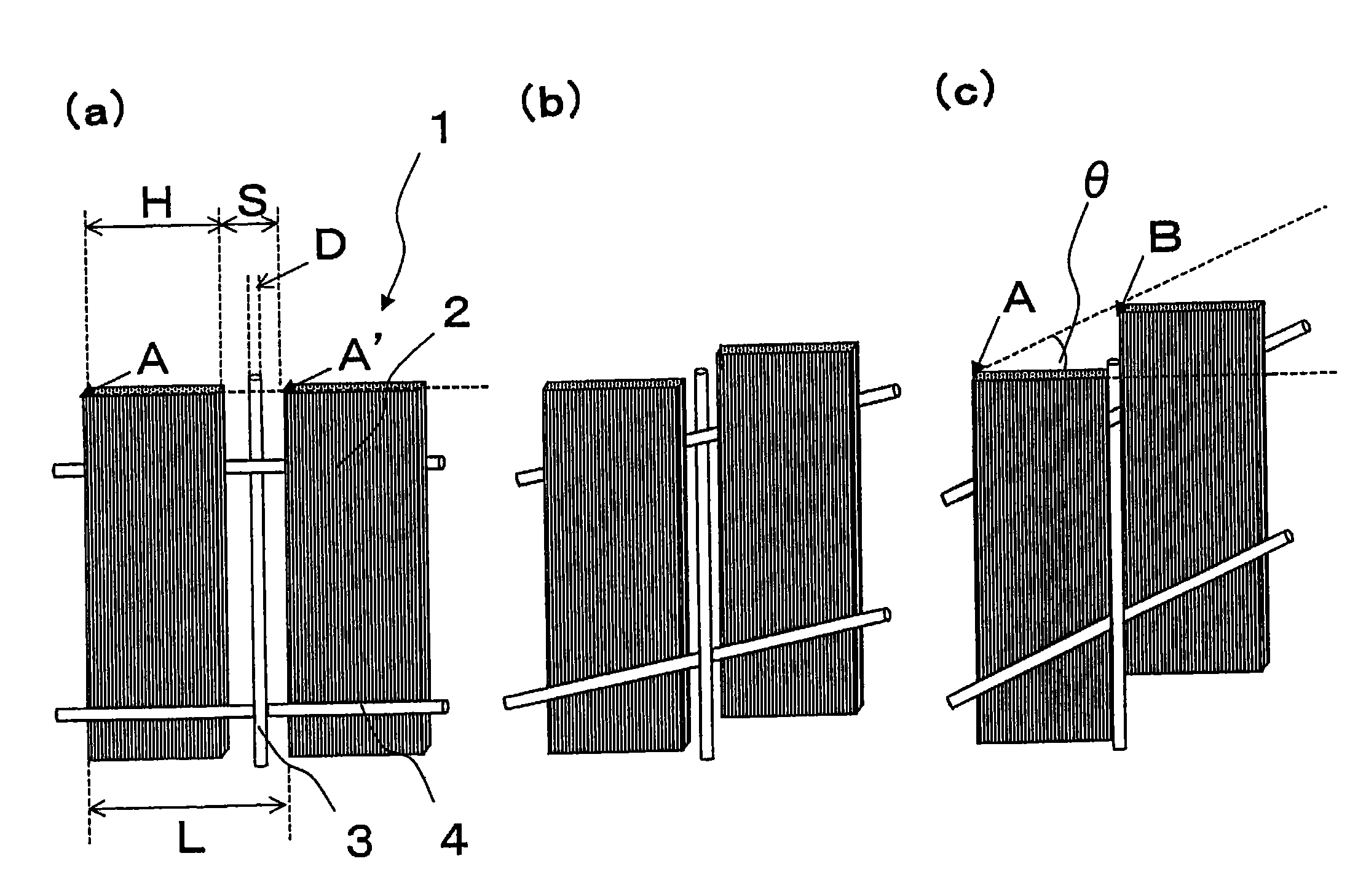
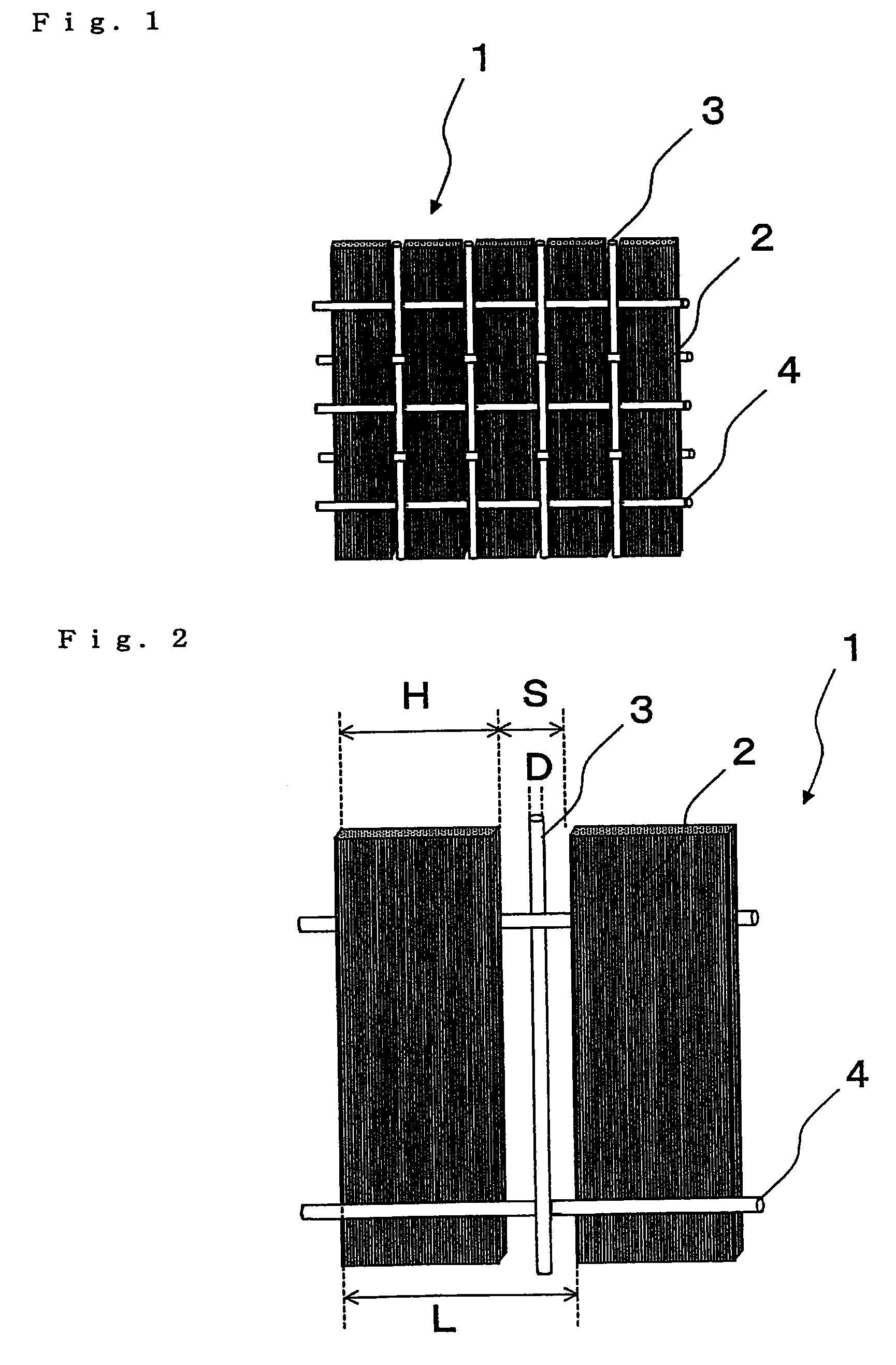
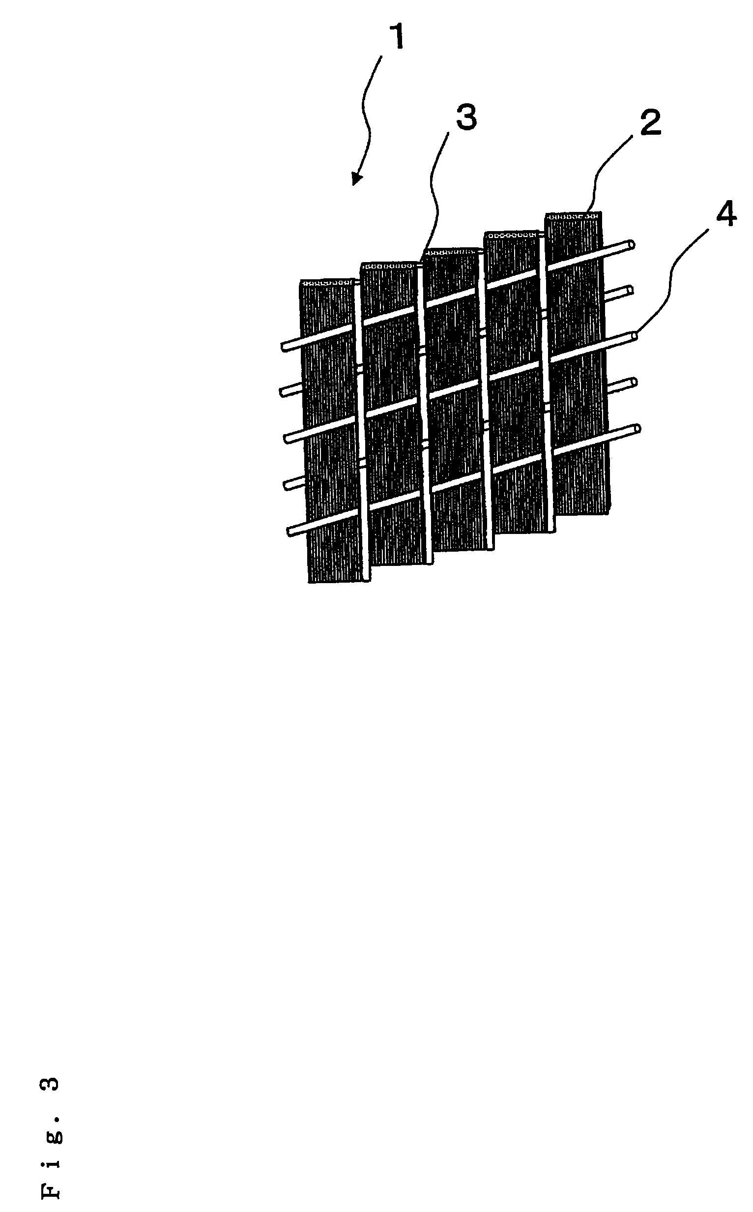

Image

  • Reinforcing fiber base material for preforms, process for the production of laminates thereof, and so on
  • Reinforcing fiber base material for preforms, process for the production of laminates thereof, and so on
  • Reinforcing fiber base material for preforms, process for the production of laminates thereof, and so on

Examples


example 1

[0276]A unidirectional, non-crimping carbon fiber woven fabric having a carbon fiber weight of 190 g / m2 was produced and used as the unidirectional reinforcing fiber base material. For the reinforcing fiber filaments, essentially untwisted carbon fiber filaments were used as the vertical fibers, the carbon fiber filaments having a filament count of 24,000, a width of 5.4 mm, a tensile strength of 5.8 GPa, a tensile elastic modulus of 290 GPa, and an amount of adhering sizing agent equal to 0.5 wt %. For the vertical auxiliary fibers, 22.5 dtex glass fibers having a coupling agent adhesed thereto and covered with 17 dtex refined nylon 66 covering fibers at 250 twists per meter were used. For the horizontal auxiliary fibers, essentially untwisted, refined, 17 dtex nylon 66 filaments were used. The woven density of the carbon fiber filaments and the vertical auxiliary fibers were both 1.84 strands / cm, the woven density of the horizontal auxiliary fibers was 3 strands / cm, and the length...

example 2

[0281]The laminate obtained in Example 1 was placed in an iron mandrel having a partially spherical shape of curvature 800 mm and a chord having two-dimensional curvature of length 350 mm, and then covered with silicon rubber of thickness 1.5 mm. After sealing the edges of the silicon rubber to the mandrel using sealant, the space formed by the mandrel and the silicon rubber was evacuated with a vacuum pump, and the laminate was pressed and draped form by the mandrel.

[0282]The laminate was then inserted into an oven while still subject to pressure by the mandrel and then heated at a temperature of 80° C. for two hours, thereby causing the sheets of carbon fiber woven fabric base material to bond together. Subsequently, the laminate was removed from the oven and cooled to room temperature, and thus a preform was obtained. After peeling off the silicon rubber from the mandrel, the preform was covered again with a bagging film, and the edges of the bagging film were sealed to the mandr...

example 3

[0284]A preform was produced identically to Example 2, except that the mandrel used was an iron mandrel having a partially spherical shape of curvature 400 mm and a chord having two-dimensional curvature length of 350 mm. Similarly to Example 2, measuring the preform reinforcing fiber volume fraction Vpf of the preform resulted in a preform reinforcing fiber volume fraction Vpf of 52%.

[0285]The obtained preform exhibited no wrinkles over the entire surface thereof, the layers of carbon fiber woven fabric base material were bonded together, and the preform favorably retained the mandrel shape.


PUM

PropertyMeasurementUnit
glass transition temperature Tgaaaaaaaaaa
widthaaaaaaaaaa

Abstract

The invention provides (1) a reinforcing fiber base material having a weave constituted of both reinforcing fiber filaments arranged in one direction in parallel with each other and auxiliary yarns arranged in another direction, which satisfies the relationship: L=H / cos θ (wherein L is the length of auxiliary yarn covering one reinforcing fiber filament and H is the width of the filament as determined in such a state where the reinforcing fiber filaments are unified only with the auxiliary yarns; and 3°≦θ (in-plane shear strain)≦30°) and wherein 2 g / m2 to 40 g / m2 of an adhesive resin having a glass transition temperature between 0° C. and 95° C. is adhesed to at least one side thereof in spots, lines, or discontinuous lines; (2) a laminate obtained by laminating layers of the above reinforcing fiber base material, wherein the adhesive resin adhesed to each layer of base material partially bonds to a facing layer of base material over the whole surface thereof, with the maximum length of each bonding joint being not less than 1 mm and not more than the width H of a reinforcing fiber filament; and (3) a preform, obtained by shaping the laminate, having a reinforcing fiber volume fraction (Vpf) of 45% to 62%.

Description

[0001]This is a U.S. National Phase application of application number PCT / JP2007 / 053157, filed Feb. 21, 2007, (which is incorporated herein by reference in its entirety), which claims priority benefit of JP 2006-052460 filed Feb. 28, 2006.TECHNICAL FIELD[0002]The present invention relates to a reinforcing fiber base material used in the production of fiber-reinforced composite materials by the resin transfer molding process (may be abbreviated hereinafter as the RTM process).[0003]In addition, the present invention further relates to the following: a reinforcing fiber base material laminate obtained by laminating and partially bonding a plurality of layers of the reinforcing fiber base material; a preform made of the reinforcing fiber base material laminate; and fiber-reinforced plastic obtained by injecting and hardening a matrix resin into the preform.[0004]More particularly, the present invention relates to a reinforcing fiber base material suitable for the production of fiber-re...

Claims


Application Information

Patent Timeline
Patent Type & Authority Patents(United States)
IPC IPC(8): B32B7/02
CPCB29B11/16B29C43/3642B29C70/20B29C70/202B29C70/226B29C70/443B32B5/26D04H3/04D04H13/002B29C43/36Y10T428/24942B29C70/46B29C2043/3644B29C2043/3652B29K2105/0854B29C70/50
Inventor SHINODA, TOMOYUKINAGAOKA, SATORUASAHARA, NOBUO
Owner TORAY IND INC
Learn More