
Sample concentration detector with temperature compensation

a technology of concentration detector and sample, applied in the field of sample sensor, can solve the problems of not being able to achieve the stability of concentration of some gases over long periods, and not being able to use a reference gas cell as a commercial product,

Inactive Publication Date: 2012-07-31
KONINK PHILIPS ELECTRONICS NV
View PDF21 Cites 5 Cited by
  • Summary
  • Abstract
  • Description
  • Claims
  • Application Information

AI Technical Summary

Benefits of technology

The invention is a sample sensor that can correct the output signal for temperature variations without using a reference gas cell. The sensor uses a temperature compensation module that compensates for the temperature-dependent wavelength shift of the light source by measuring a temperature-dependent parameter of the light source and adjusting the output wavelength accordingly. The sensor can be a photo acoustic detector or a photodiode. The calibration factor for temperature compensation is determined through a calibration measurement at various temperatures using a known calibration concentration and a known calibration driving current. The technical effect of the invention is to provide a sample sensor that can accurately compensate for temperature-dependent wavelength shifts, without the need for a reference gas cell.

Problems solved by technology

Although this approach can be used for fundamental studies in research institutes, the use of a reference gas cell is not a preferred approach for a commercial product.
Because the reference gas cell signal is based on absorption, a long reference gas cell is required which is not attractive for a compact sensor or a high concentration needs to be used which in case of, for example, NO2 becomes dangerous when the reference gas cell accidentally breaks.
Furthermore it is a problem of the reference gas cell, that the concentration of some gases is not stable over long periods due to for instance wall sticking or dissociation.

Method used


Image

  • Sample concentration detector with temperature compensation
  • Sample concentration detector with temperature compensation
  • Sample concentration detector with temperature compensation

Examples


Embodiment Construction

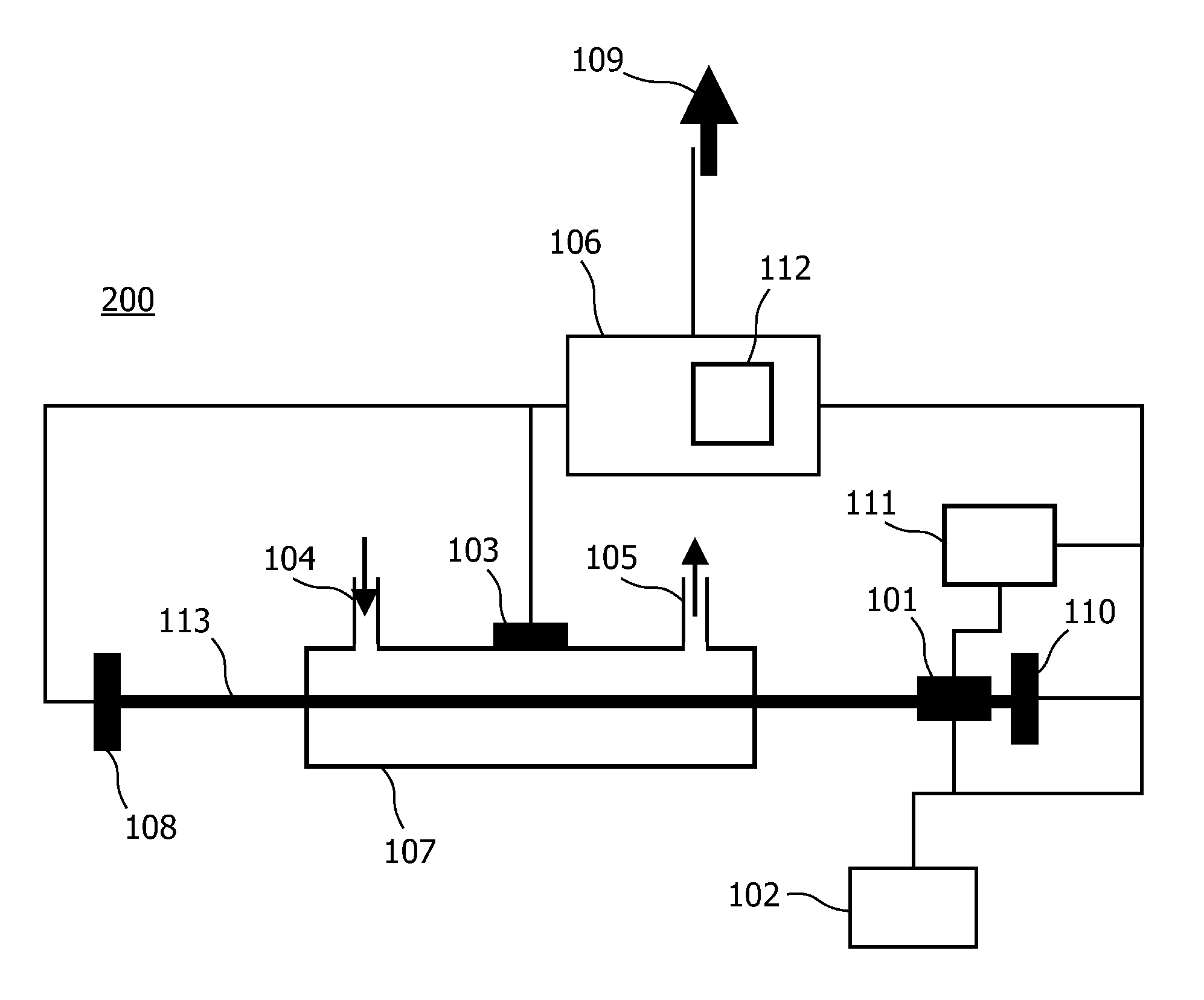
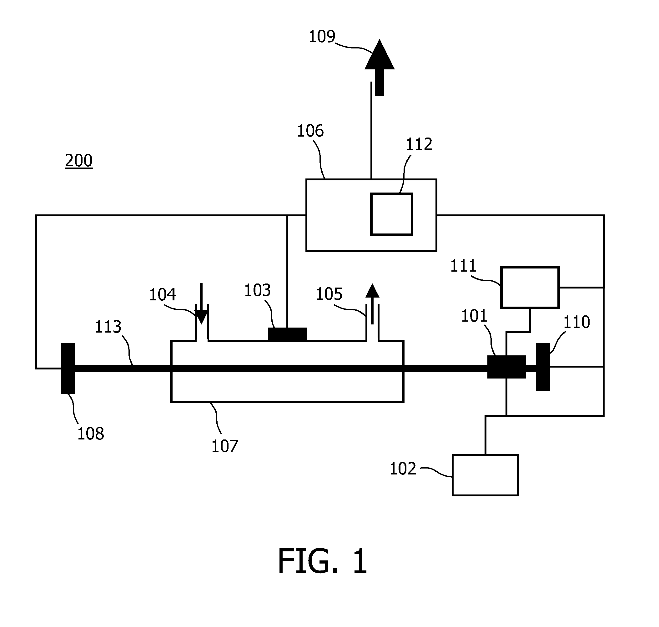
[0032]FIG. 1 schematically shows an embodiment of the sample sensor 200 according to the invention. The sample sensor 200, shown in FIG. 1 is a photo acoustic detector, which is also arranged for detecting sample concentrations based on optical absorption. The description below primarily describes the photo acoustic detector, but a skilled person could easily understand that the temperature compensation works in the same way when using optical absorption for measuring the concentration. Optionally, both techniques are used in parallel for obtaining more reliable measurements.

[0033]The photo acoustic trace gas detector 200 described hereinafter detects trace gas concentrations in a gas mixture, but the invention may also be applied to detect tissue, fluid or solid samples in other sample mixtures. The gas mixture to be tested is comprised in the gas cell 107. The gas cell 107 may comprise a gas inlet 104 and a gas outlet 105 for filling and emptying the gas cell 107. In an apparatus ...


PUM

PropertyMeasurementUnit
temperaturesaaaaaaaaaa

Abstract

A sample sensor (200) for detecting a concentration of a sample in a sample mixture, the sample sensor (200) comprising a light source (101), a detector element, a processing section (106) and parameter measuring means. The light source (101) produces a light beam (113) for exciting molecules of the sample. The detector element detects an 5 amount of excited molecules of the sample and provides a detector current indicating the amount. The processing section (106) is coupled to the detector element (103) for processing the detector current to generate an output signal (109) representing the concentration. The processing section (106) comprises a temperature compensation module (112) being arranged for compensating for a temperature dependent wavelength shift of the light source (101) 10 based on at least one measured value of a temperature dependent parameter of the light source (101), other than an output wavelength. The parameter measuring means obtain the at least one measured value.

Description

TECHNICAL FIELD OF THE INVENTION[0001]The invention relates to a sample sensor for detecting a concentration of a sample in a sample mixture, the sample sensor comprising a light source for producing a light beam for exciting molecules of the sample, a detector element for detecting an amount of excited molecules of the sample and providing a detector current indicating the amount and a processing section, coupled to the detector element for processing the detector current to generate an output signal representing the concentration, the sample sensor further comprising means for compensating for a temperature dependent wavelength shift of the light source.BACKGROUND OF THE INVENTION[0002]Such a sample sensor is known from U.S. Pat. No. 6,552,792. This US patent describes a wavelength modulated photo acoustic spectrometry system and method for measuring a concentration of a trace gas in a gas mixture. The method comprises generating light from a light source; passing the light throug...

Claims


Application Information

Patent Timeline
Patent Type & Authority Patents(United States)
IPC IPC(8): G01N21/00G01K17/00
CPCG01N21/1702G01N21/274G01N21/3504G01N2201/1211
Inventor VAN KESTEREN, HANS W.
Owner KONINK PHILIPS ELECTRONICS NV
Learn More