
Control apparatus and control method for internal combustion engine

a control apparatus and control method technology, applied in the direction of electric control, engine starters, machines/engines, etc., can solve the problems of not much fuel adhesion to the intake port prior to startup, corresponding large amount of unburned hydrocarbons (hc), and it takes a certain amount of time for the catalyst to activa

Active Publication Date: 2012-07-24
TOYOTA JIDOSHA KK
View PDF6 Cites 27 Cited by
  • Summary
  • Abstract
  • Description
  • Claims
  • Application Information

AI Technical Summary

Benefits of technology

This patent describes a control apparatus and method for an internal combustion engine that reduces the amount of unburned HC (HC) during startup and shutdown. The control apparatus includes a startup operating portion and a shutoff operating portion. The startup operating portion starts the engine by supplying fuel to only a portion of the cylinders, while the shutoff operating portion stops the engine by stopping the supply of fuel to the remaining cylinders. This reduces the amount of fuel required to start the engine and also helps to reduce the amount of residual HC when the engine is shut down. The control method also includes adjusting the crank angle when stopping the engine to make a specific cylinder the initial firing cylinder. Overall, this technology helps to minimize emissions and improve engine performance during startup and shutdown.

Problems solved by technology

Moreover, not much fuel is adhered to the intake port prior to startup.
However, when a large amount of fuel is supplied, a corresponding large amount of unburned hydrocarbons (HC) is discharged from the cylinders to the exhaust pipe.
Although a catalyst for purifying the exhaust gas is provided in the exhaust pipe, it takes a certain amount of time for the catalyst to activate (or more specifically, for the purifying ability of the catalyst to activate) at startup when the temperature of the catalyst is low.
However, this air includes unburned HC that had been adhered to the intake port and the inside wall of the cylinder and the like.
As a result, with the technology in JP-A-8-338282, even though activation of some of the cylinders is delayed in order to reduce the amount of unburned HC that is discharged, a large amount of unburned HC may end up being discharged from those delay activated cylinders.

Method used


Image

  • Control apparatus and control method for internal combustion engine
  • Control apparatus and control method for internal combustion engine
  • Control apparatus and control method for internal combustion engine

Examples


Embodiment Construction

[0024]A first example embodiment of the invention will now be described with reference to FIGS. 1 to 4.

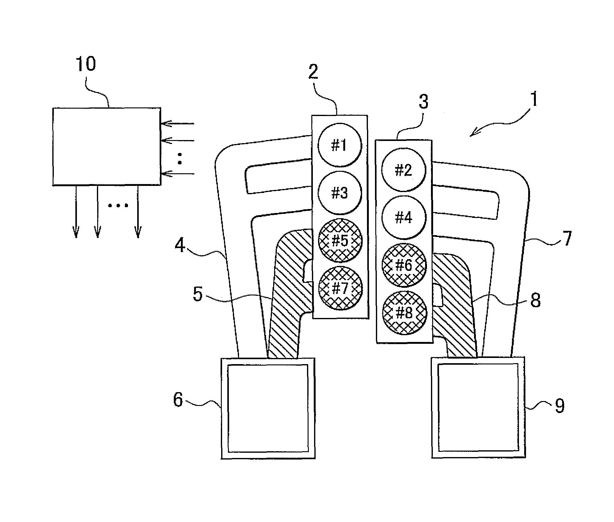
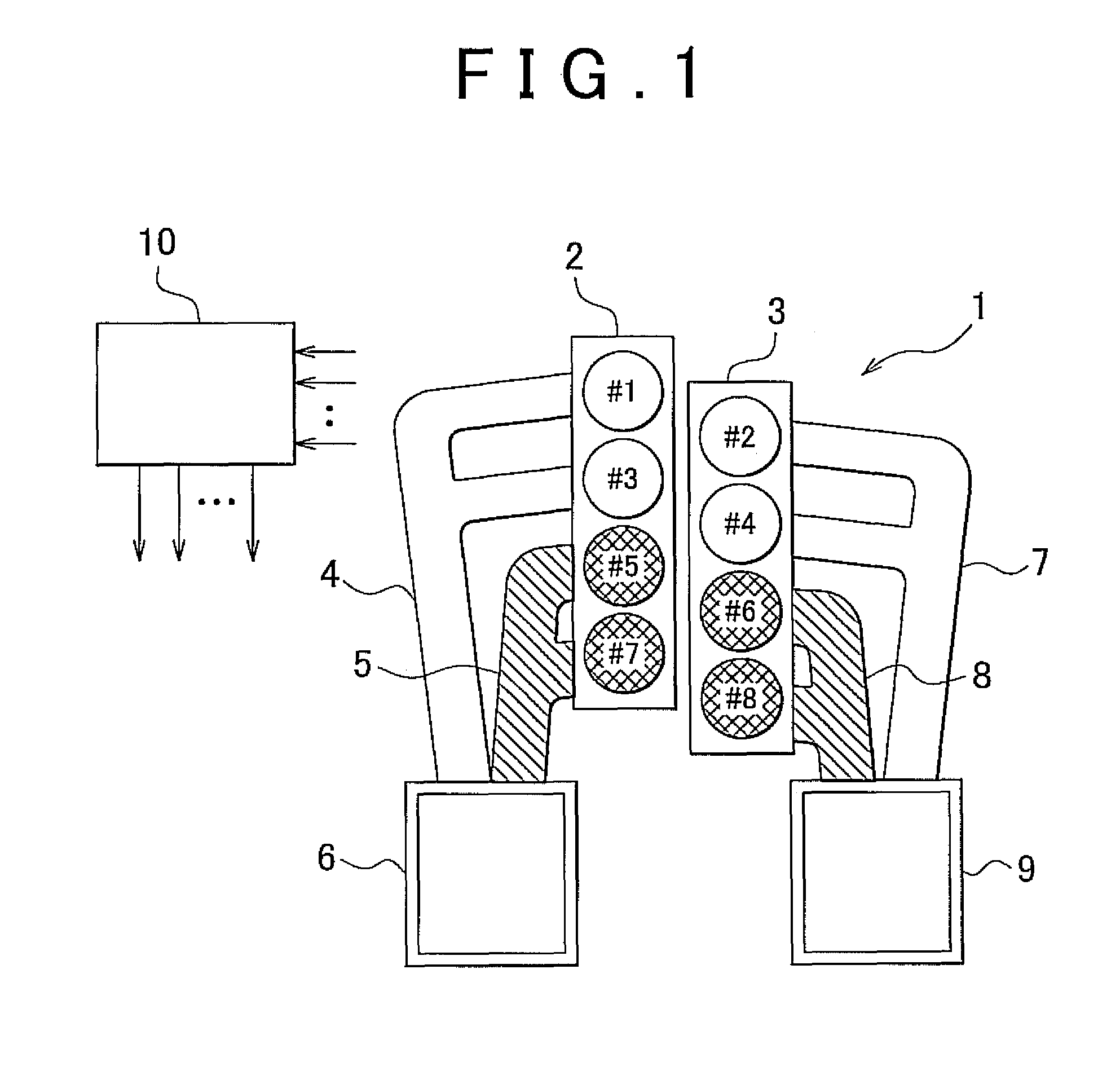
[0025]FIG. 1 is a view of the structure of a multiple cylinder internal combustion engine (hereinafter, simply referred to as “engine”) to which the control apparatus of the first example embodiment may be applied. The engine 1 shown in FIG. 1 is a V-8 four-stroke reciprocating engine that has eight cylinders. The reference numbers from #1 to #8 in FIG. 1 indicate the specific cylinder number given to each cylinder. In the example shown in FIG. 1, in a left bank 2, an exhaust manifold 4 is connected to the #1 cylinder and the #3 cylinder that are located away from a catalyst 6, and an exhaust manifold 5 is connected to the #5 cylinder and the #7 cylinder that are located near the catalyst 6. The two exhaust manifolds 4 and 5 are connected in parallel to the catalyst 6. Also, in a right bank 3, an exhaust manifold 7 is connected to the #2 cylinder and the #4 cylinder that are locate...


PUM


Abstract

In a startup operation of an internal combustion engine, the internal combustion engine is started by supplying fuel to only a first cylinder group formed of a portion of cylinders, from among a plurality of cylinders that make up the internal combustion engine, when a startup condition of the internal combustion engine has been satisfied, and then fuel starts to be supplied to a second cylinder group formed of the remaining cylinders after the internal combustion engine has started. Meanwhile, in a stopping operation of the internal combustion engine, the internal combustion engine is stopped when a shutoff condition of the internal combustion engine is satisfied, by first stopping the supply of fuel to the second cylinder group and then stopping the supply of fuel to the first cylinder group after the supply of fuel to the second cylinder group has been stopped.

Description

CROSS-REFERENCE TO RELATED APPLICATIONS[0001]This application claims priority to Japanese Patent Application No. 2010-009243 filed on Jan. 19, 2010, which is incorporated herein by reference in its entirety including the specification, drawings and abstract.BACKGROUND OF THE INVENTION[0002]1. Field of the Invention[0003]The invention relates to a control apparatus and a control method for an internal combustion engine. More particularly, the invention relates to a control apparatus and a control method for a multiple cylinder internal combustion engine.[0004]2. Description of the Related Art[0005]Although some fuel that is injected from a fuel injection valve into an intake port in an internal combustion engine vaporizes immediately, the rest of the fuel temporarily adheres to the wall surface of the intake port. The fuel that has adhered to the intake port vaporizes from negative pressure inside the intake pipe or the heat from the wall surface of the intake port and, together with...

Claims


Application Information

Patent Timeline
Patent Type & Authority Patents(United States)
IPC IPC(8): F02D41/06
CPCF02D41/0082F02D41/0087F02D41/042F02D41/047F02D41/061F02D41/062F02D2041/0092F02D2041/0095
Inventor ASO, KOJITANAKA, HIROSHI
Owner TOYOTA JIDOSHA KK
Learn More