
Image forming apparatus

a technology of forming apparatus and forming curve, which is applied in the direction of electrographic process apparatus, instruments, optics, etc., can solve the problems of increasing the curve of the speed of each of the ymc photoconductors, increasing the curve of the speed of the k photoconductors during the period, and affecting the speed of the predetermined process, etc., to achieve the effect of increasing load

Active Publication Date: 2012-07-10
SHARP KK
View PDF11 Cites 3 Cited by
  • Summary
  • Abstract
  • Description
  • Claims
  • Application Information

AI Technical Summary

Benefits of technology

[0015]The present invention is accomplished in view of the circumstance described above, and aims to provide a technique for compensating a rotational phase of each photoconductor without using a complicated and expensive detecting mechanism so as to be capable of suppressing a color misregistration caused by a misregistration in rotational phases, in an image forming apparatus including plural photoconductors, each forming an image that is to be superimposed. In other words, a misregistration in a rotational phase, which is caused upon starting a photoconductor driven by a first drive section and a photoconductor driven by a second drive section after they are stopped, can be prevented.
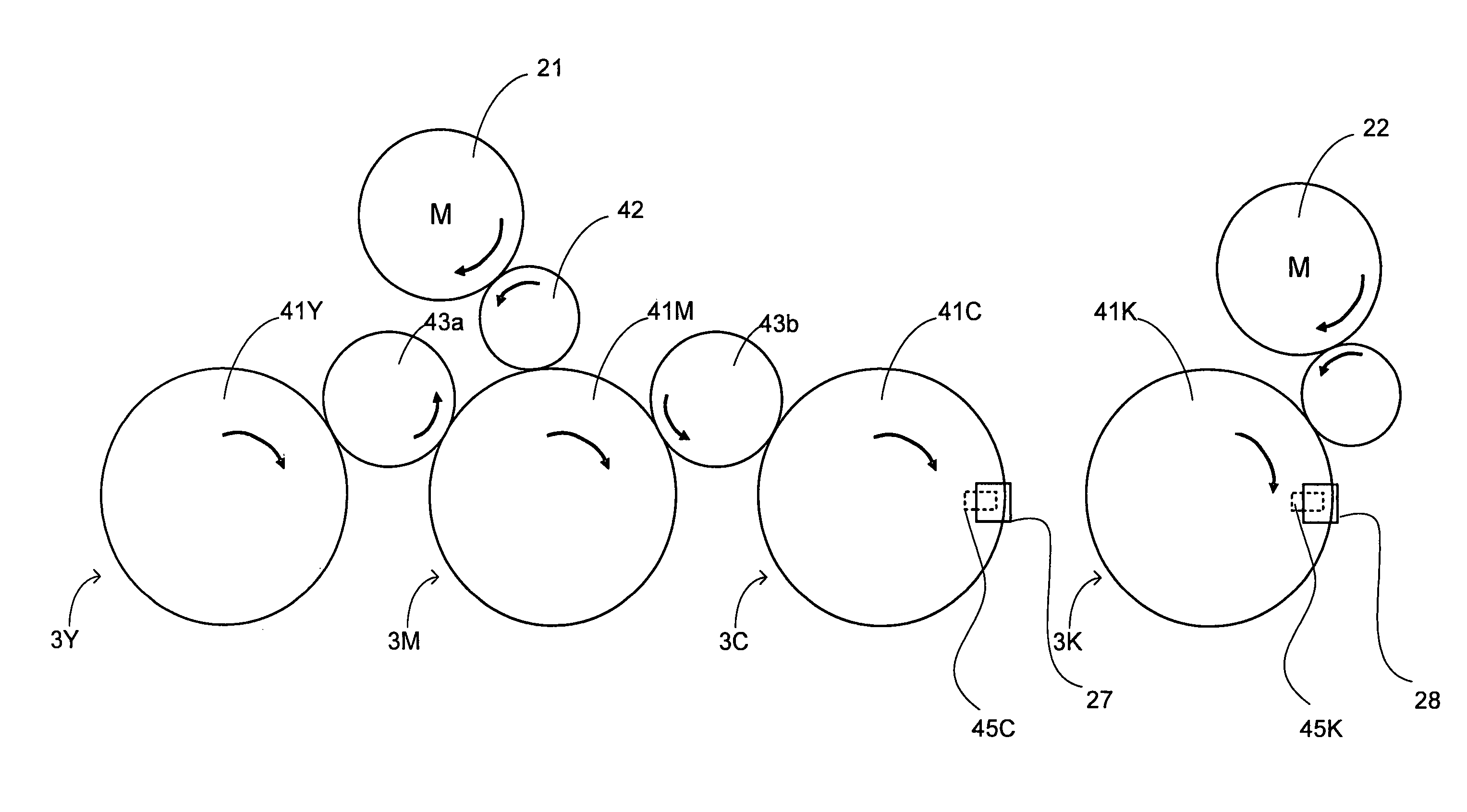
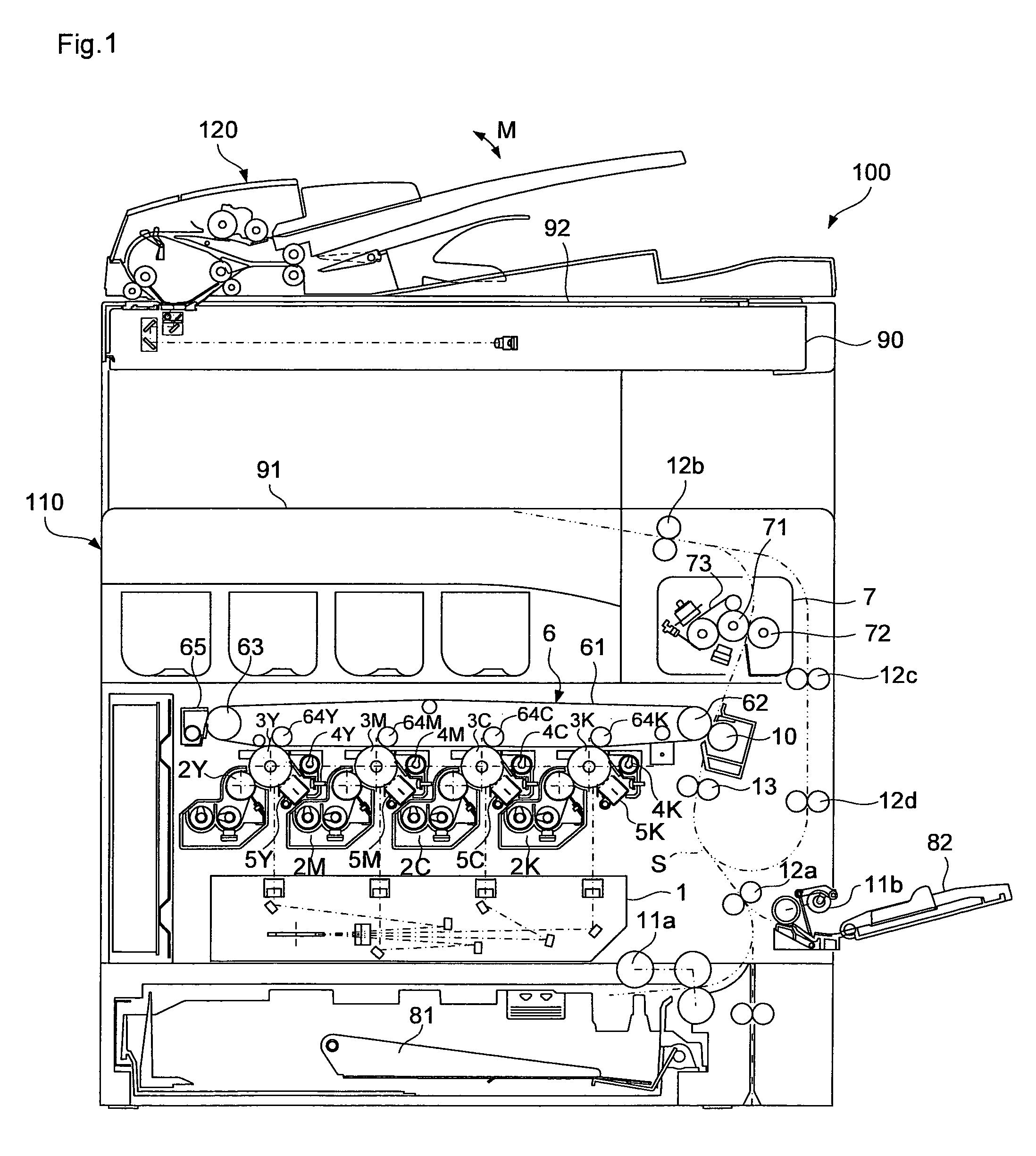
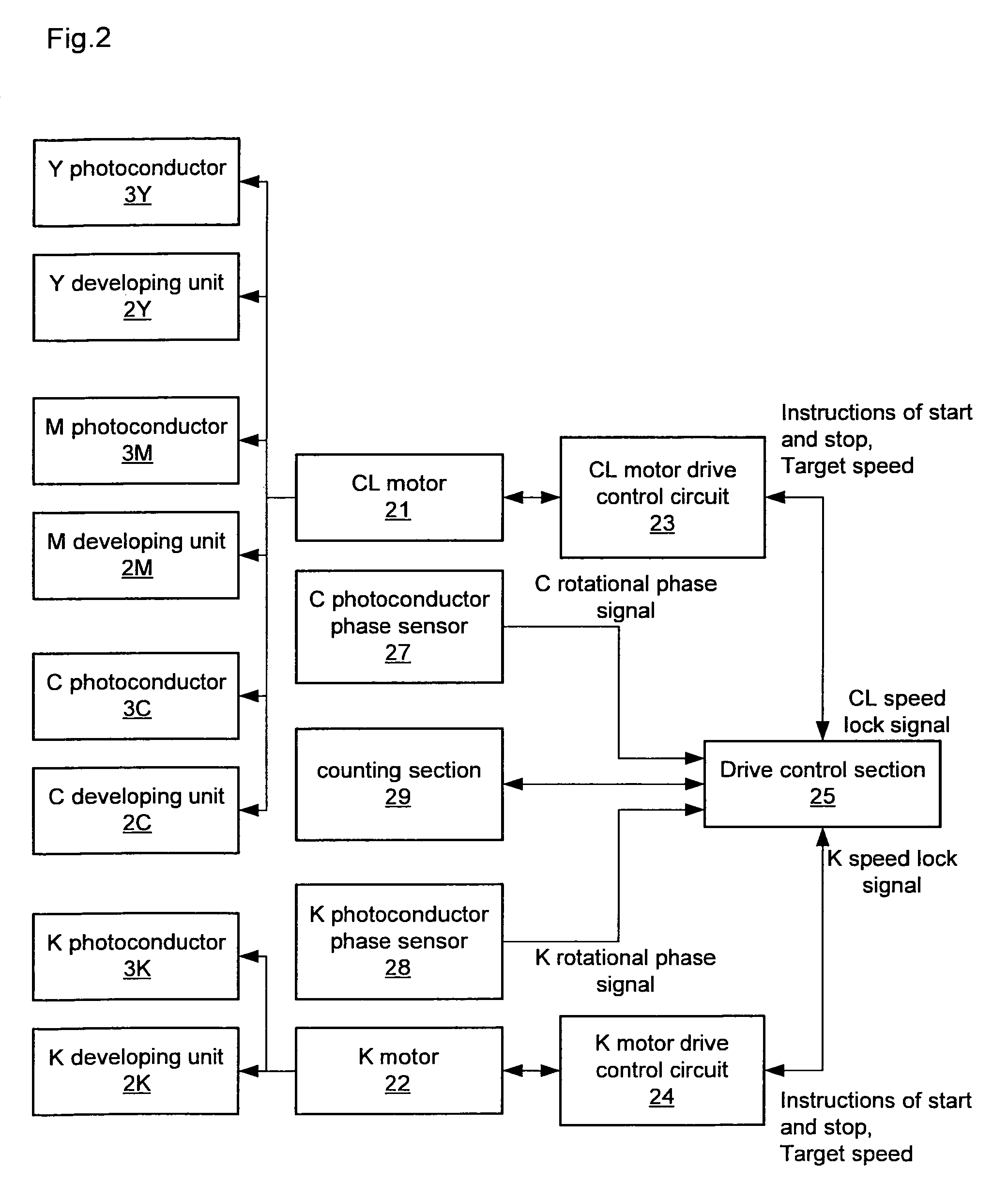
[0017]In the image forming apparatus according to the present invention, the drive control section controls so that the first drive section is started after a lapse of a predetermined startup delay time after the second drive section is started, when each of the photoconductors is started to, wherein the startup delay time is predetermined based on the result of the counted time of the first and the second drive sections. Therefore, the rotational phase of each photoconductor can be compensated without employing a complicated and expensive detecting mechanism, whereby a color misregistration caused by a misregistration in rotational phases can be prevented. Specifically, upon the starting, the drive section, which starts the first photoconductor group, is driven a predetermined time after the start of the rotation by the drive section that drives the second photoconductor group, which has a greater load. Accordingly, the misregistration in the rotational phases due to the difference in the loads can be reduced.

Problems solved by technology

A DC motor may sometimes be used for the other colors in order to share a control circuit and a control program with K. However, the problems described below arise when the DC motor is used for the drive.
However, when a DC motor is used, an increase curve of the speed of each of the YMC photoconductors and an increase curve of the speed of the K photoconductor during the period from when the respective photoconductors are started to when they reach a predetermined process speed might not be matched.
Further, the technique needs to employ an absolute-type rotary encoder, which is expensive, for the detection of the phase.

Method used


Image

  • Image forming apparatus
  • Image forming apparatus
  • Image forming apparatus

Examples


Embodiment Construction

[0036]In the present invention, a mono-color image is formed by using one or more color components, and further, formed by using color components less than those for a full-color image. When the mono-color image is formed by plural color components, a color phase of the image is substantially uniform in each region. In an embodiment described later, a mono-color image is constituted of only a K color component. Specifically, the first photoconductor group is constituted of only one photoconductor. This is a general embodiment. It is to be noted that there is an embodiment, for example, in which photoconductors are used for a high-density region and a low-density region since more emphasis is placed on a grayscale. In the present invention, a mono-color means a single phase. It is not necessarily a black. For example, the mono-color may be red as a special use. In this case, two color components of Y and M correspond to the first photoconductor group. The first photoconductor group m...


PUM


Abstract

An image forming apparatus including: a first and a second photoconductor groups constituted of one or more photoconductors respectively; a first and a second drive control sections for controlling the drive of the first and the second photoconductor groups respectively to rotate the photoconductors thereof, wherein the rotational phases of the first photoconductor group and the second photoconductor group are adjusted to be matched therebetween; and the first and the second drive control sections control so that predetermined profile of a target speed is applied to the first and second photoconductor groups wherein, in the target-speed profile, the first photoconductor group starts rotating after a elapse of a predetermined startup delay time from the second photoconductor group starts rotating, and both groups end at a same final speed predetermined for full-color image formation, wherein the startup delay time is predetermined based on measurements of times needed for each of the first and the second photoconductor groups to reach a predetermined speed from starting the rotation with the target-speed profile being applied thereto.

Description

CROSS-REFERENCE TO RELATED APPLICATION[0001]This application is related to Japanese Patent Application No. 2008-155681 filed on Jun. 13, 2008, whose priority is claimed and the disclosure of which is incorporated by reference in its entirety.BACKGROUND OF THE INVENTION[0002]1. Field of the Invention[0003]The present invention relates to an image forming apparatus having plural photoconductors.[0004]2. Description of the Related Art[0005]There has been known an image forming apparatus, so-called tandem type image forming apparatus, in which plural toner images are formed by means of plural photoconductors, each corresponding to each toner image, with an electrophotographic process, and these toner images are superimposed. In a tandem type image forming apparatus that forms a full-color image, toner images of respective color components, such as yellow (Y), magenta (M), cyan (C), and black (K), are formed by means of different photoconductors, and each of the toner images is superimpo...

Claims


Application Information

Patent Timeline
Patent Type & Authority Patents(United States)
IPC IPC(8): G03G15/00
CPCG03G15/0131G03G15/5008G03G2215/0132G03G2215/0161
Inventor MOCHIZUKI, SHUICHIITO, TETSUSHIAKAMATSU, HIROTSUGUSASOH, KIYOSHIKUMAGAI, YUUJIYAMAGUCHI, TETSUYA
Owner SHARP KK
Learn More