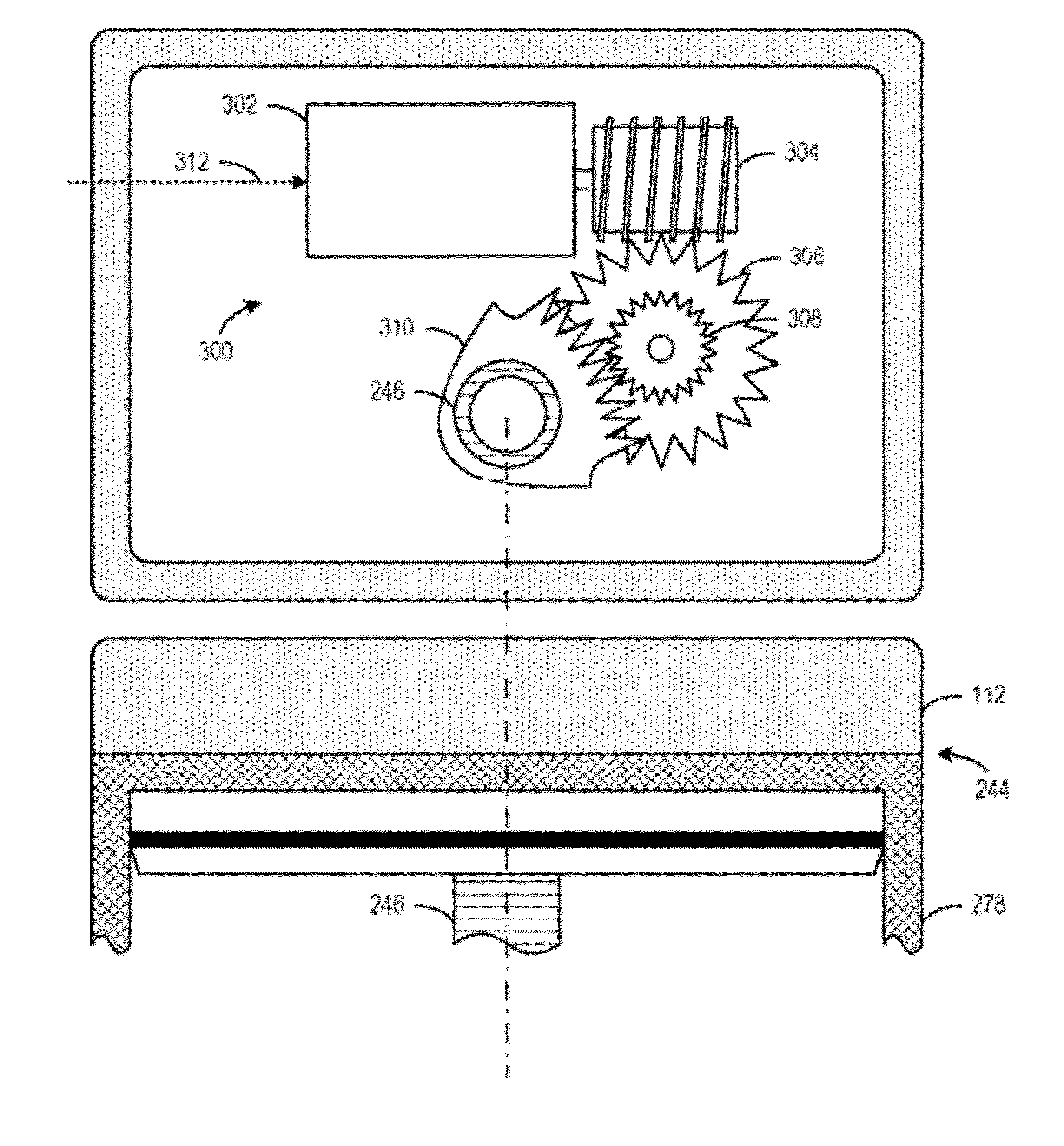
Fuel system with electrically-controllable mechanical pressure regulator

a technology of mechanical pressure regulator and fuel system, which is applied in the direction of electric control, positive displacement liquid engine, machines/engines, etc., can solve the problems of reducing engine power and efficiency, fuel may not sufficiently mix with the air in the cylinder, and insufficient mixing, so as to improve fuel injection accuracy, reduce energy consumption, and improve durability

Inactive Publication Date: 2012-07-03
FORD GLOBAL TECH LLC
View PDF65 Cites 15 Cited by
  • Summary
  • Abstract
  • Description
  • Claims
  • Application Information

AI Technical Summary

Benefits of technology

[0002]Many internal combustion engines utilize Gasoline Direct Injection (GDI) to increase the power efficiency and range over which the fuel can be delivered to the cylinder. One potential issue with GDI is that under lower fuel pressures the fuel may not sufficiently mix with the air in the cylinder. Insufficient mixing may decrease engine power and efficiency, and increase emissions, at least under some conditions. For example, during cold engine starts, and before the catalytic converter is activated, insufficient mixing as a result of lower fuel pressure may exacerbate cold start emissions.
[0003]In one example, a fuel delivery system includes a lower pressure fuel pump and a high pressure fuel pump in combination to achieve a higher fuel pressure. However, at startup the two-pump system may require a longer duration to pump fuel at the higher fuel pressure, which may result in engine miss-starts. Further, the slow response time of the fuel pumps may allow for pulsations in fuel pressure to cause inaccurate amounts of fuel to be injected for combustion. Moreover, the consistently higher fuel pressure may cause increased wear on components of the fuel delivery system.
[0005]By implementing a mechanical fuel pressure regulator having a spring preload that may be mechanically maintained and adjusted via operation of an electric motor, fuel pressure pulsations may be compensated for quickly and a set-point fuel pressure may be adjusted dynamically during various operating conditions. In this way, fuel pressure may be regulated consistently, which in turn may improve fuel injection accuracy. Moreover, the electric motor of the fuel pressure regulator may be operated to adjust the spring preload and then the adjusted spring preload may be maintained mechanically. By only operating the electric motor to make spring preload adjustments energy consumption may be reduced and durability may be improved.
[0007]By increasing the spring preload and maintaining it in preparation for the next engine start, the set-point fuel pressure may already be established and activation of the low pressure pump flow may be dedicated to replenishing the high pressure pump immediately instead of waiting for set-point fuel pressure adjustment at startup (e.g., key-on) for quicker fueling and engine starting. This approach may provide faster closed loop fuel pressure control during startup and during low engine fuel consumption conditions. Moreover, by utilizing a preload of a spring in the fuel pressure regulator to adjust fuel pressure, the fuel pressure set-point may be decreased after startup to reduce wear on fuel delivery system components. In this way, the operational lifetime of the fuel delivery system may be increased. The above described approaches may provide high control accuracy to dynamically adjust the set-point fuel pressure whether it be to dampen pressure pulsations during vehicle operation or to enable quicker and more robust engine starts.

Problems solved by technology

One potential issue with GDI is that under lower fuel pressures the fuel may not sufficiently mix with the air in the cylinder.
Insufficient mixing may decrease engine power and efficiency, and increase emissions, at least under some conditions.
For example, during cold engine starts, and before the catalytic converter is activated, insufficient mixing as a result of lower fuel pressure may exacerbate cold start emissions.
However, at startup the two-pump system may require a longer duration to pump fuel at the higher fuel pressure, which may result in engine miss-starts.
Further, the slow response time of the fuel pumps may allow for pulsations in fuel pressure to cause inaccurate amounts of fuel to be injected for combustion.
Moreover, the consistently higher fuel pressure may cause increased wear on components of the fuel delivery system.

Method used


Image

  • Fuel system with electrically-controllable mechanical pressure regulator
  • Fuel system with electrically-controllable mechanical pressure regulator
  • Fuel system with electrically-controllable mechanical pressure regulator

Examples


Embodiment Construction

[0014]The present disclosure is related to a fuel system for a vehicle having an electrically controllable mechanical fuel pressure regulator, as well as methods for controlling the electrically controllable mechanical fuel pressure regulator to make fuel injection more accurate and robust. The approaches may provide fast closed loop fuel pressure regulation with the use of a mechanical pressure regulator. Further, commanding the fuel pressure to a designated set-point may be performed in a simple manner by positioning a spring preload of the mechanical fuel pressure regulator. Further still, such an approach may reduce or eliminate the need for damper components in the fuel system which may reduce costs of the fuel system. Further still, by operating the electric motor when adjusting the set-point fuel pressure and mechanically maintaining the set-point, the mechanical fuel pressure regulator component life may be improved relative to a fuel pressure regulator that maintains the se...


PUM


Abstract

A method for operating an engine direct injection fuel system is provided. The direct injection fuel system includes a mechanical fuel pressure regulator that has a spring actuatable by an electric motor. The method includes adjusting a preload of the spring by operating the electric motor to adjust a set-point fuel pressure from a first set-point fuel pressure to a second set-point fuel pressure in response to an operating condition, and maintaining the preload of the spring mechanically when the electric motor is not operating.

Description

CROSS-REFERENCE TO RELATED APPLICATIONS[0001]This application claims priority from U.S. Provisional Patent Application No. 61 / 222,216, entitled “Fuel System with Electrically-Controllable Mechanical Pressure Regulator,” filed Jul. 1, 2009, the disclosure of which is hereby incorporated by reference in its entirety and for all purposes.BACKGROUND AND SUMMARY[0002]Many internal combustion engines utilize Gasoline Direct Injection (GDI) to increase the power efficiency and range over which the fuel can be delivered to the cylinder. One potential issue with GDI is that under lower fuel pressures the fuel may not sufficiently mix with the air in the cylinder. Insufficient mixing may decrease engine power and efficiency, and increase emissions, at least under some conditions. For example, during cold engine starts, and before the catalytic converter is activated, insufficient mixing as a result of lower fuel pressure may exacerbate cold start emissions.[0003]In one example, a fuel deliver...

Claims


Application Information

Patent Timeline
Patent Type & Authority Patents(United States)
IPC IPC(8): F02M59/36
CPCF02D41/042F02D41/064F02D41/3854F02M37/0029F02M37/0058F02M69/54F02D41/0087F02D41/0255F02D2200/0602Y10T137/85986
Inventor KOKOTOVIC, VLADIMIR V.KOLMANOVSKY, ILYA VLADIMIRWANG, YAN
Owner FORD GLOBAL TECH LLC
Why Eureka
Try Eureka