
Climate control system and method for optimizing energy consumption of a vehicle

a technology of climate control system and vehicle energy consumption, which is applied in the direction of process and machine control, refrigeration machines, propulsion parts, etc., can solve the problems of increasing fuel consumption, increasing the load on the engine, and using a relatively large amount of energy for the operation of air conditioning compressor and/or cooling fan

Active Publication Date: 2012-06-26
FORD GLOBAL TECH LLC
View PDF26 Cites 30 Cited by
  • Summary
  • Abstract
  • Description
  • Claims
  • Application Information

AI Technical Summary

Benefits of technology

[0008]In the case of a hybrid electric vehicle (HEV), operation of an electric compressor and a cooling fan often necessitates starting the engine to ensure that the battery is not over-discharged. One of the benefits of an HEV is the fuel savings achieved by driving the vehicle using electric motor power, while maximizing the time the engine is shut down. Thus, inefficient operation of the climate control system can offset some of the benefits gained by driving an HEV. Accordingly, a need exists for a system and method for vehicle climate control that strikes a balance between meeting the comfort requirements of vehicle occupants and minimizing the overall power consumed by the climate control system.

Problems solved by technology

One limitation of such systems is that operation of the air conditioning compressor and / or the cooling fan uses a relatively large amount of energy.
In the case of a conventional vehicle, where the engine mechanically drives the compressor, the increased load on the engine reduces efficiency and increases fuel consumption.
Opportunities for controlling climate control systems to improve fuel economy are limited because the compressor power consumption depends upon the speed of the engine.
Further, hot air mixing done to achieve a desired target discharge temperature often results in significant energy waste.
Thus, inefficient operation of the climate control system can offset some of the benefits gained by driving an HEV.

Method used


Image

  • Climate control system and method for optimizing energy consumption of a vehicle
  • Climate control system and method for optimizing energy consumption of a vehicle
  • Climate control system and method for optimizing energy consumption of a vehicle

Examples


Embodiment Construction

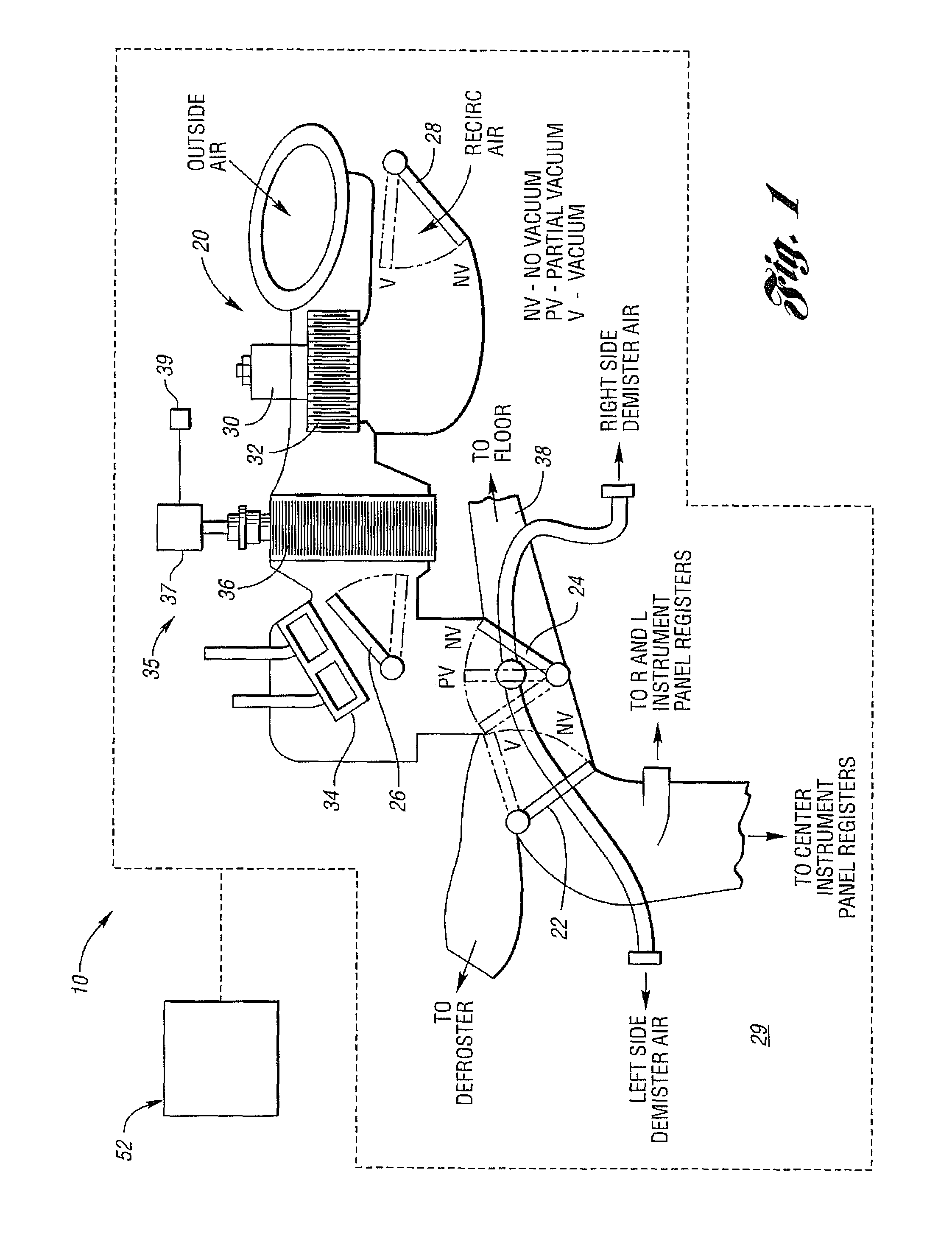
[0017]In general, control of cabin temperature, as well as temperature and defogging of a windshield, within an automobile is accomplished using various actuators to adjust the temperature and flow of air supplied to the cabin of the vehicle. FIG. 1 schematically shows an exemplary system 10 for environmental management of a vehicle in accordance with an embodiment of the present application. The vehicle may include a heating, ventilating and air conditioning (HVAC) system, generally indicated at 20. The HVAC system 20 can include the arrangement of airflow doors, including panel-defrost, floor-panel, and outside recirculated air actuators or doors 22, 24, and 28, respectively.

[0018]The doors may be part of an air distribution system for directing the flow of conditioned air to various locations within a passenger cabin 29 of the vehicle, such as to the windshield, floor, or instrument panel as is commonly known. The doors 22, 24 and 28 may be driven by vacuum motors (not shown) bet...


PUM


Abstract

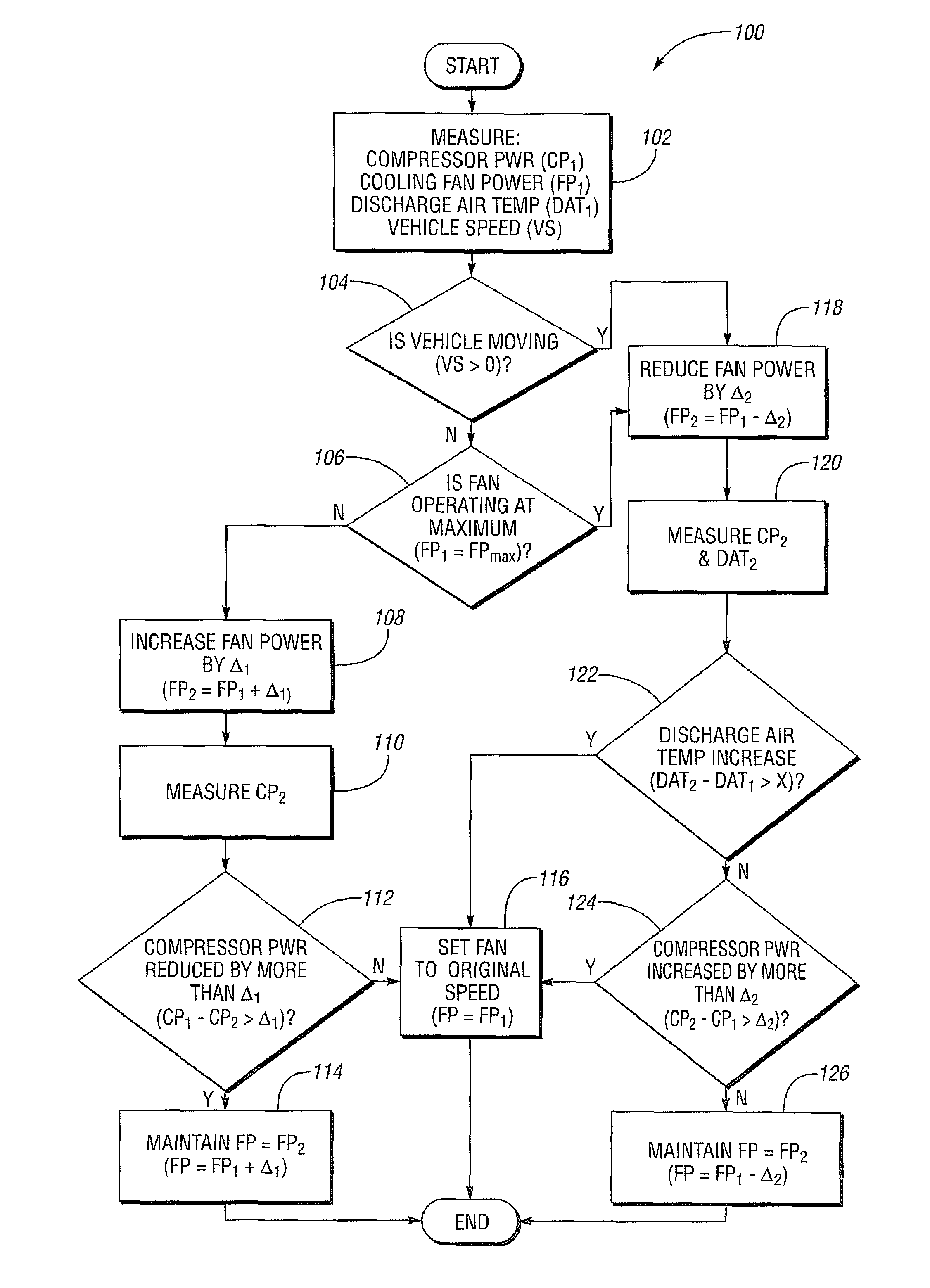
A climate control system and method for optimizing energy consumption in a hybrid electric vehicle (HEV) is provided. By varying evaporator temperatures based on occupant settings and environmental conditions, electric compressor speed can be optimized to provide the necessary cooling capacities resulting in energy savings. Determining the impact that increasing or decreasing engine cooling fan speed has on the overall energy consumption of the climate control system without affecting target discharge air temperature provides for energy saving opportunities. Optimizing energy consumption according to the provided strategy provides for improved fuel economy without sacrificing passenger comfort.

Description

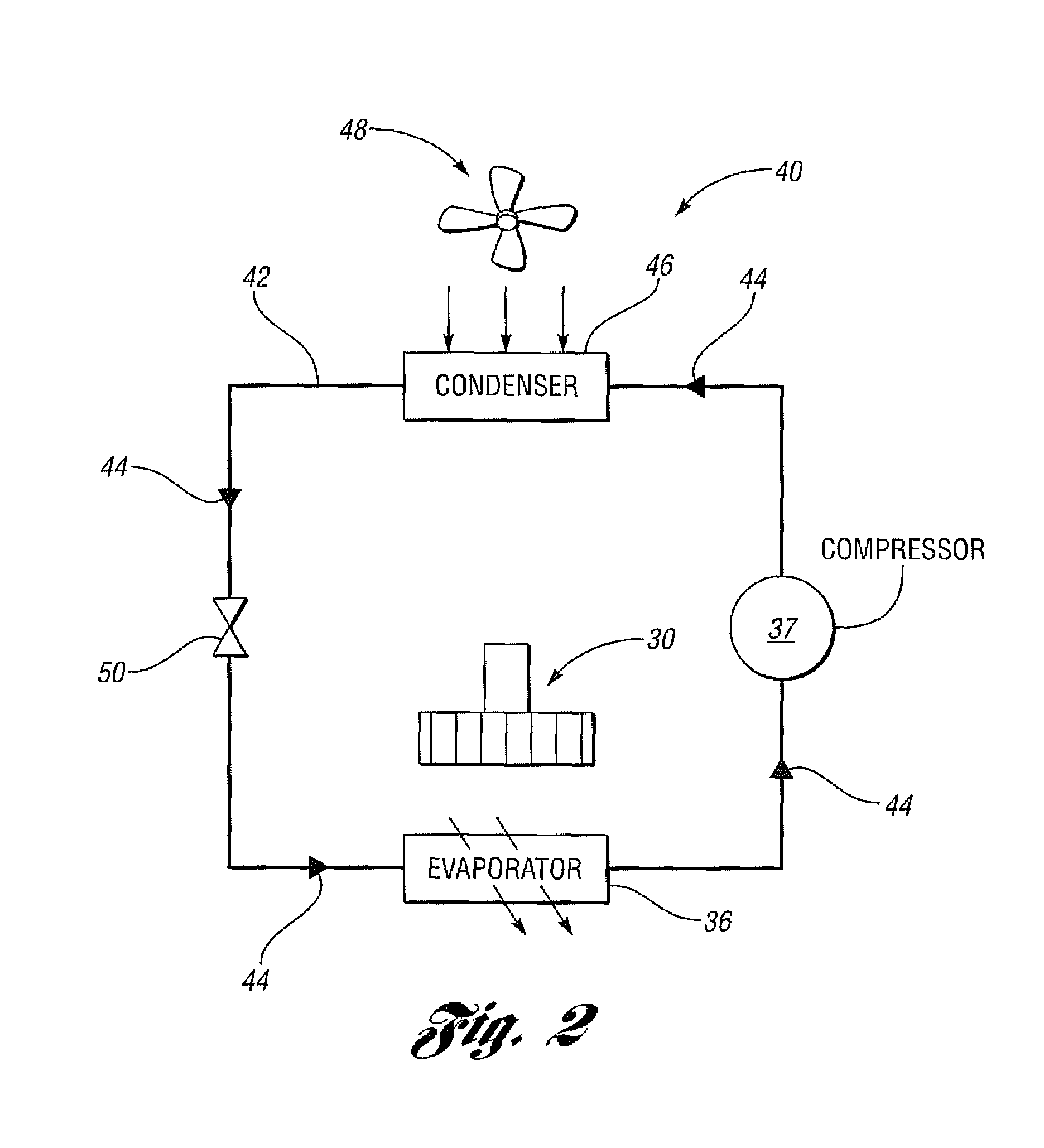
BACKGROUND[0001]1. Technical Field[0002]The present invention relates to a climate control system and method for optimizing energy consumption in a vehicle.[0003]2. Background Art[0004]Automatic climate control is increasingly prevalent in vehicles today. In some vehicles, a driver merely chooses a temperature setting, and a control system operates a climate control system to achieve the desired temperature. The climate control system may control the functions of a fan—e.g., on / off and fan speed—and an air conditioning system. Such a climate control system may also control the position and movement of various air dampers, or air flow doors, to control movement of air through an evaporator core or a heater core, the recirculation of air through the vehicle, the intake of fresh air, or some combination thereof.[0005]The air conditioning system uses an air conditioning compressor and a condenser to effectuate cooling of a passenger cabin of the vehicle. A cooling fan is disposed adjace...

Claims


Application Information

Patent Timeline
Patent Type & Authority Patents(United States)
IPC IPC(8): B60H1/00
CPCB60H1/3205B60H2001/3238B60H2001/3266B60H2001/3277
Inventor WIJAYA, HALIMDAGE, GERHARD A.BUESCHER, WAYNE FRANKGREINER, CHRISTOPHER MARK
Owner FORD GLOBAL TECH LLC
Learn More