Method and apparatus for biological wastewater purification

a biological wastewater and purification technology, applied in water/sludge/sewage treatment, specific water treatment objectives, moving filter element filters, etc., can solve the problems of limiting the performance of the wastewater purification plant, increasing the hydraulic load of the activated sludge tank and secondary clarifier tank, and large amount of energy required for the pumps, etc., to achieve easy and effective separation and high performance density

Inactive Publication Date: 2012-06-12
UNIVERSITY OF KASSEL
View PDF19 Cites 4 Cited by
  • Summary
  • Abstract
  • Description
  • Claims
  • Application Information

AI Technical Summary

Benefits of technology

[0011]The invention can be used with special advantage in the case of problem sludge. This includes sludge with voluminous sludge structures such as bulking sludge or sludge with solid components that tend to cause clogging or have a high fiber content, because the problem substances can be separated off and removed, whereas they are concentrated in the known methods. Also, the method can be reliably operated because an incomplete solid / liquid separation does not tend to cause clogging on account of the separated amount, which is large in comparison to a membrane. The method can be readily retrofitted for existing wastewater-purification methods, so that an expensive expansion of waste treatment plants is avoided.
[0012]A filtration that is conducted so that part of the solids is removed with the liquid phase can be carried out readily and with a reliable operation with a significant part of the activated sludge being retained.
[0015]High performance density is achieved with a dry substance content in the activated sludge tank of 3 to 8 g / l for conventional activated sludge methods or 8 to 20 g / l, preferably 10 to 15 g / l for membrane-activated sludge methods without problems occurring in the aeration.

Problems solved by technology

This limits the performance of the wastewater purification plant and increases the hydraulic load on the activated sludge tank and secondary clarifier tank.
Furthermore, a large amount of energy is required for the pumps.
The use of lamellar separators, e.g. in the outlet of the activated sludge tank, has not proven itself because in this case, as in settling tanks, only gravity is at work and because the removal of the thickened sludge is problematic.
Therefore, on the whole the solid content in the activated sludge tank is limited at the top.
A high flow rate and in the case of a separate filtration tank a high recirculation rate must be maintained; this has the result that even unpurified wastewater passes to the filter membrane due to bypasses, which can lead to premature fouling.
The rake is not suitable for concentrating activated sludge in an activated sludge tank.
This apparatus is not suitable for increasing the biological purification performance in an activated sludge tank.

Method used


Image

  • Method and apparatus for biological wastewater purification
  • Method and apparatus for biological wastewater purification
  • Method and apparatus for biological wastewater purification

Examples


Embodiment Construction

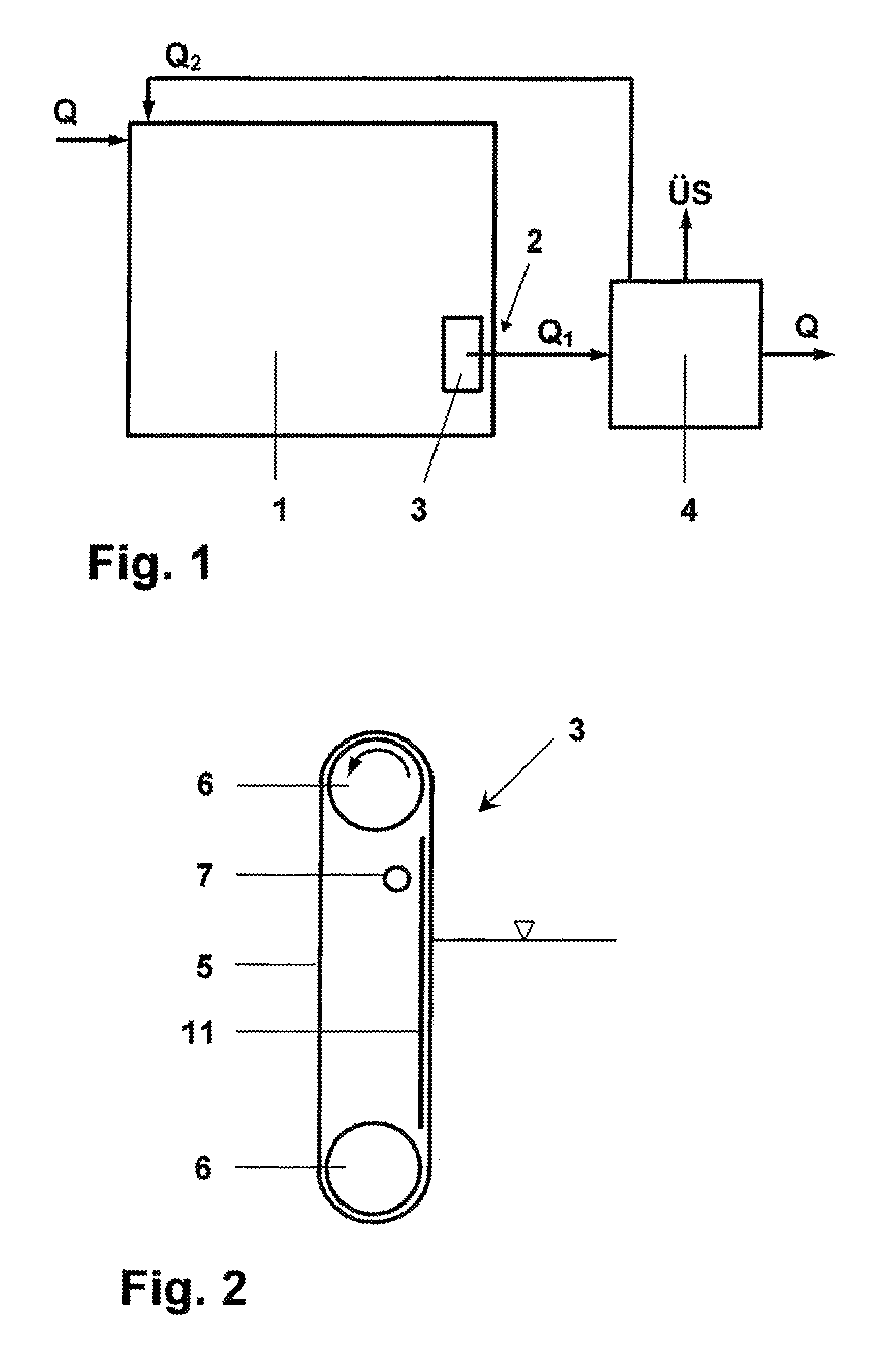
[0022]As is apparent from FIG. 1 a wastewater stream Q is continuously introduced into an activated sludge tank 1 where it is intensively mixed with a wastewater / activated-sludge mixture for a predetermined average residence time. At the same time, the mixture is aerated, as a result of which dissolved substances are biologically degraded. The means for the thorough mixing and aeration are not shown. The activated sludge tank 1 is followed by a secondary clarification tank 4. From here, a return sludge stream Q2 is recycled, if necessary, to the activated sludge tank 1.

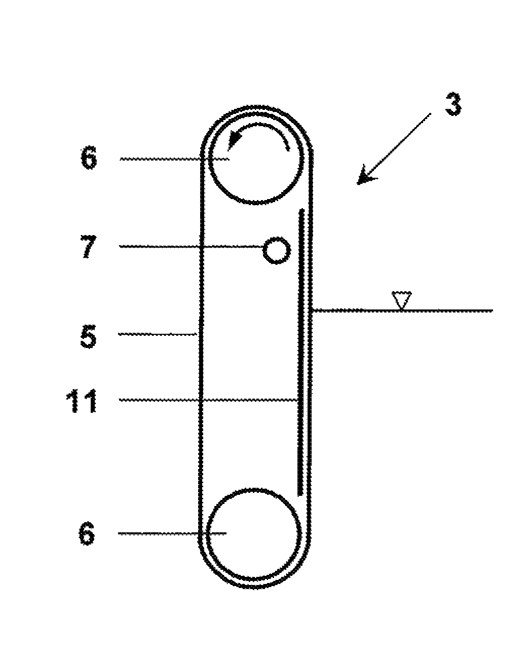
[0023]An apparatus 3 for the incomplete solid / liquid separation is provided in a drain 2 of the activated sludge tank 1 in such a manner that the entire draining mixture amount Q1 (=Q+Q2) is treated here. The apparatus 3 comprises in this example according to FIG. 2 an endless sieve belt 5 guided over two horizontal rollers 6 mounted vertically above the other. One of the rollers 6 can be driven in such a manner that ...


PUM

PropertyMeasurementUnit
sizeaaaaaaaaaa
sizeaaaaaaaaaa
densityaaaaaaaaaa

Abstract

A biological wastewater is mixed in an activated sludge tank with activated sludge that is concentrated in the activated sludge tank to a predetermined value. The mixture of wastewater and activated sludge running off in a drain of the activated sludge tank is then sieved to effect an incomplete solid / liquid separation that leaves a separated solid phase in the activated sludge tank. The liquid phase including a remnant of solids is then removed from the tank.

Description

CROSS REFERENCE TO RELATED APPLICATIONS[0001]This application is the US national stage of PCT application PCT / EP2007 / 006462, filed 20 Jul. 2007, published 31 Jan. 2008 as WO2008 / 012030, and claiming the priority of German patent application 102006034984.9 itself filed 28 Jul. 2006, whose entire disclosures are herewith incorporated by reference.FIELD OF THE INVENTION[0002]The invention relates to a method of biological wastewater purification in which wastewater is mixed in an activated sludge tank with activated sludge and in which the activated sludge present in the activated sludge tank is concentrated to a predetermined value as well as to an apparatus having an inlet and an outlet and set up for carrying out the method of this invention.BACKGROUND OF THE INVENTION[0003]In the conventional activated sludge method, cleaning performance is achieved in an activated sludge tank by activated sludge (bacterial sludge). In order to concentrate active biomass in the activated sludge tan...

Claims


Application Information

Patent Timeline
Patent Type & Authority Patents(United States)
IPC IPC(8): C02F3/00
CPCC02F3/1273C02F1/44C02F2303/24Y02W10/10
Inventor FRECHEN, FRANZ-BERNDSCHIER, WERNFRIED
Owner UNIVERSITY OF KASSEL
Why Eureka
Try Eureka