
Programmable duty cycle distortion generation circuit

a technology of distortion generation and duty cycle, applied in the direction of line-transmission details, transmission monitoring, instruments, etc., can solve the problems of circuit must cope and errors in the operation of the integrated circuit to aris

Active Publication Date: 2012-05-15
INTEGRATED DEVICE TECH INC
View PDF65 Cites 19 Cited by
  • Summary
  • Abstract
  • Description
  • Claims
  • Application Information

AI Technical Summary

Benefits of technology

The patent describes an integrated circuit that includes a serial transmitter, a serial receiver, and a serial connection for communication between them. The circuit also includes a duty cycle distortion circuit that distorts the duty cycle of a signal within the circuit to stress test it. This allows for on-chip testing of the integrated circuit without the need for expensive off-chip testing equipment. The duty cycle distortion circuit can be controlled by a duty cycle distortion control circuit that determines the degree of distortion applied to the duty cycle. The integrated circuit can be self-timed serial data communication, and the accurate transmission and reception of this communication depends on well-timed duty cycles, which can be tested by distorting the duty cycle of a signal within the integrated circuit. The technical effect of this patent is to provide a simple and easily programmable method for stress testing integrated circuits with cost-effective components.

Problems solved by technology

This distortion of the duty cycle of the signal creates a stress with which the integrated circuit must cope, if it is to continue operating as it would if no distortion had been applied.
If the duty cycle of a signal exceeds the tolerances of components of the integrated circuit which receive that signal, then errors in the operation of the integrated circuit will arise.

Method used


Image

  • Programmable duty cycle distortion generation circuit
  • Programmable duty cycle distortion generation circuit
  • Programmable duty cycle distortion generation circuit

Examples


Embodiment Construction

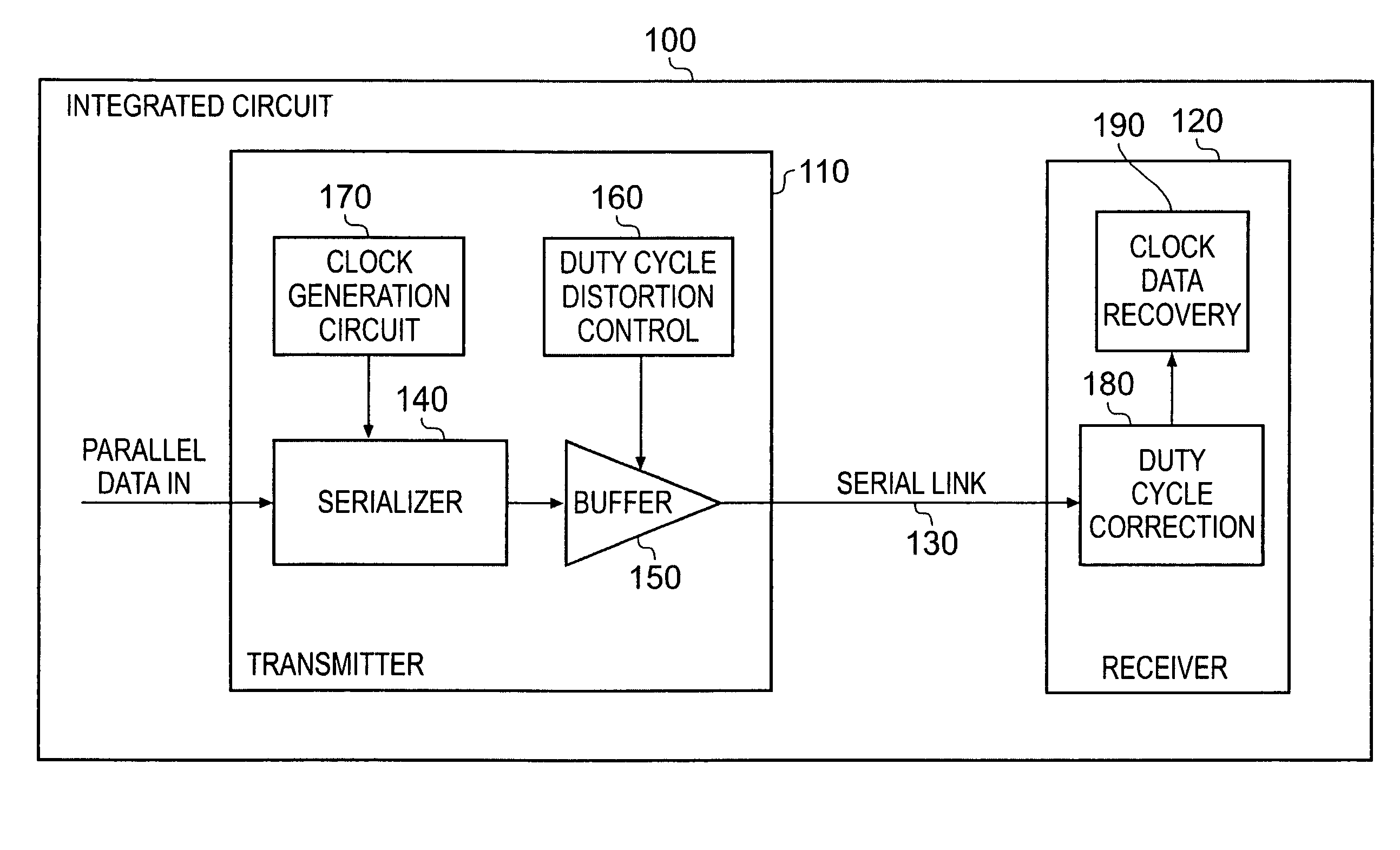
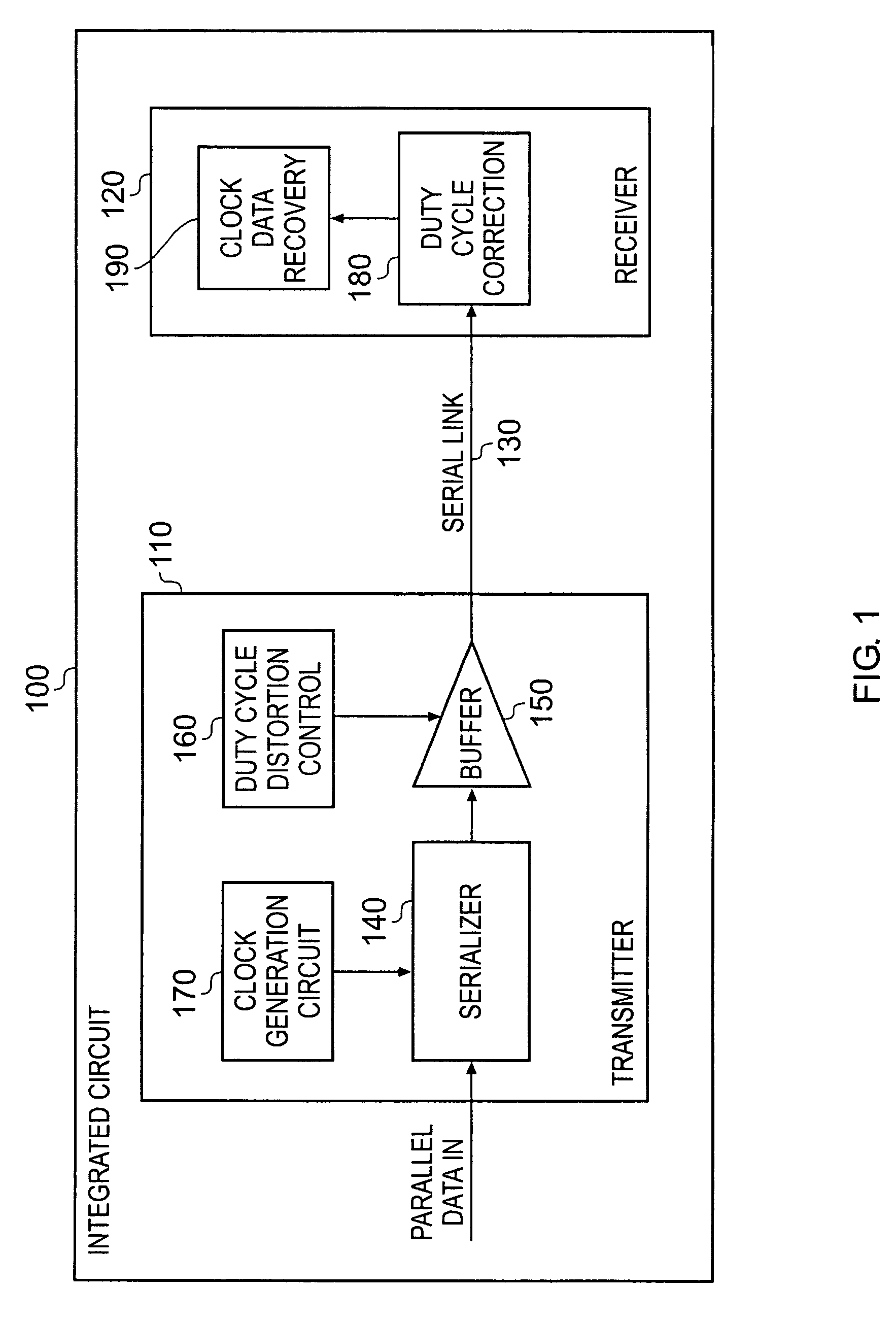
[0029]FIG. 1 schematically illustrates an integrated circuit 100, comprising a serial transmitter 110, a serial receiver 120 and a serial link 130. Serial link 130 connects serial transmitter 110 to serial receiver 120. Serial transmitter 110 receives parallel data and serializes it with serializer 140 for transmission over serial link 130. In this embodiment serializer 140 generates self-timed serial data. This is done with reference to a clock signal received from clock generation circuit 170. On the transmission path leading out of serializer 140 is a data buffer 150, through which the serialized data passes on its way to serial link 130. Also connected to data buffer 150 is duty cycle distortion control unit 160. Within data buffer 150 is a duty cycle distortion circuit configured to distort a duty cycle of the serialized data passing though the buffer. This distortion is carried out under the control of duty cycle distortion control unit 160 by means of a duty cycle control sig...


PUM


Abstract

An integrated circuit is provided comprising: a serial transmitter, a serial receiver and a serial connection providing communication between the serial transmitter and the serial receiver. The integrated circuit further comprises a duty cycle distortion circuit so that the integrated circuit can be stress tested by distorting the duty cycle of a signal within the integrated circuit.

Description

BACKGROUND OF THE INVENTION[0001]1. Field of the Invention[0002]The present invention relates to stress testing integrated circuits. More particularly, this invention relates to stress testing integrated circuits in which serial data is communicated by altering the duty cycle of a signal within that integrated circuit.[0003]2. Description of the Prior Art[0004]It is known to perform tests on integrated circuits comprising serial receivers which receive serialized data from serial transmitters over high speed serial links. Such testing, for example shortly after manufacturing, involves artificially downgrading the quality of the signal sent over the serial link in order to test how well the serial receiver copes with that poor quality data and whether it can still recover the original data that was transmitted. A receiver's ability to cope with such distorted signals is referred to as its jitter tolerance.[0005]Typically, a external programmable signal generator is used to provide th...

Claims


Application Information

Patent Timeline
Patent Type & Authority Patents(United States)
IPC IPC(8): H04B3/46
CPCG01R31/31715H04B3/462G01R31/31708
Inventor THURSTON, JASONGRAY, CARL THOMAS
Owner INTEGRATED DEVICE TECH INC
Learn More