
Mailing machine transport system including a guide to reduce the impact on the weighing device caused by the trailing edge of the mailpeice

a technology of mail machine and weighing device, which is applied in the field of mail processing system, can solve the problems of scale oscillation, non-delivery of mail pieces, loss of funds, etc., and achieve the effects of reducing the weight of more mail pieces, improving the throughput of the mail machine, and fast weighing of mail pieces

Active Publication Date: 2012-05-15
PITNEY BOWES INC
View PDF22 Cites 16 Cited by
  • Summary
  • Abstract
  • Description
  • Claims
  • Application Information

AI Technical Summary

Benefits of technology

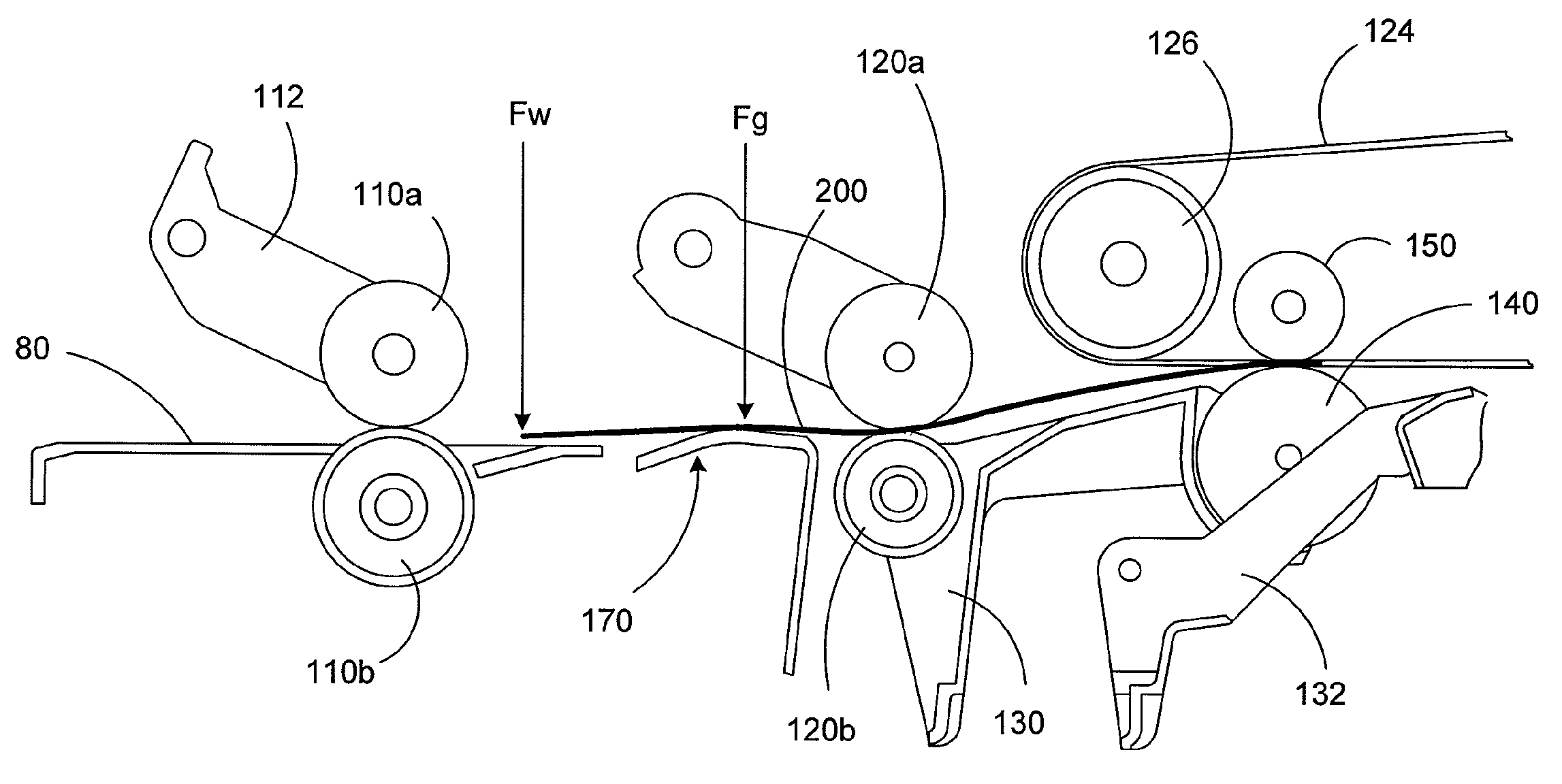
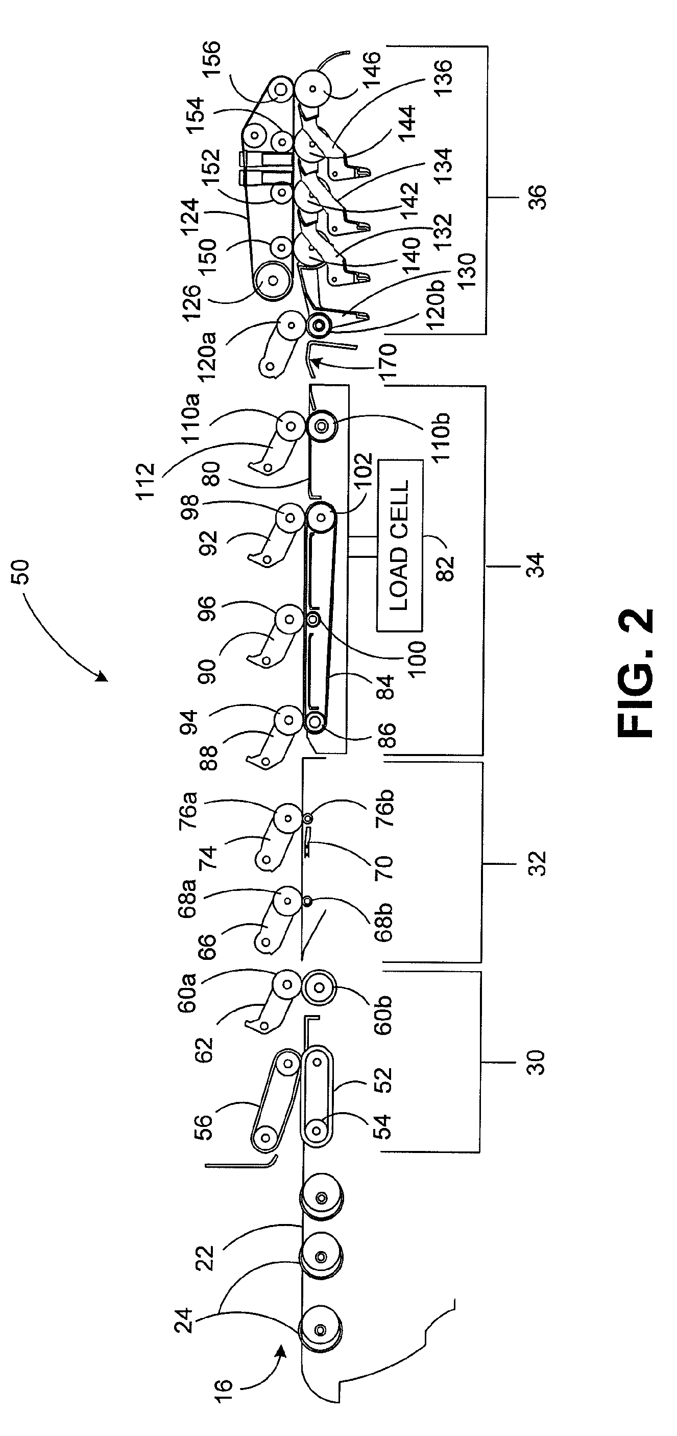
"The present invention is a mail processing system that reduces external forces on the scale, allowing for faster weighing of mail pieces. A guide piece is provided in the transport path between the weighing module and the subsequent module, which causes the trail edge of a mail piece to remain at the same level as or lift away from the weighing platform, thereby significantly reducing, if not eliminating, any forces from the trail edge of the exiting mail piece as the weighing module acquires the first peak in the waveform signal for weighing the subsequent mail piece. This allows for a fast weighing algorithm that utilizes only the first peak and increases the throughput of the mailing machine."

Problems solved by technology

If the weighing module does not accurately weigh a mail piece or determine that it is below the threshold amount, the amount of postage applied to the mail piece will either be too little, resulting in possible non-delivery of the mail piece, or too much, resulting in a loss of funds.
A basic cause of the delay in determining weight for a mail piece is the tendency of the scale to oscillate when a mail piece is being transported (or stopped) on the scale.

Method used


Image

  • Mailing machine transport system including a guide to reduce the impact on the weighing device caused by the trailing edge of the mailpeice
  • Mailing machine transport system including a guide to reduce the impact on the weighing device caused by the trailing edge of the mailpeice
  • Mailing machine transport system including a guide to reduce the impact on the weighing device caused by the trailing edge of the mailpeice

Examples


Embodiment Construction

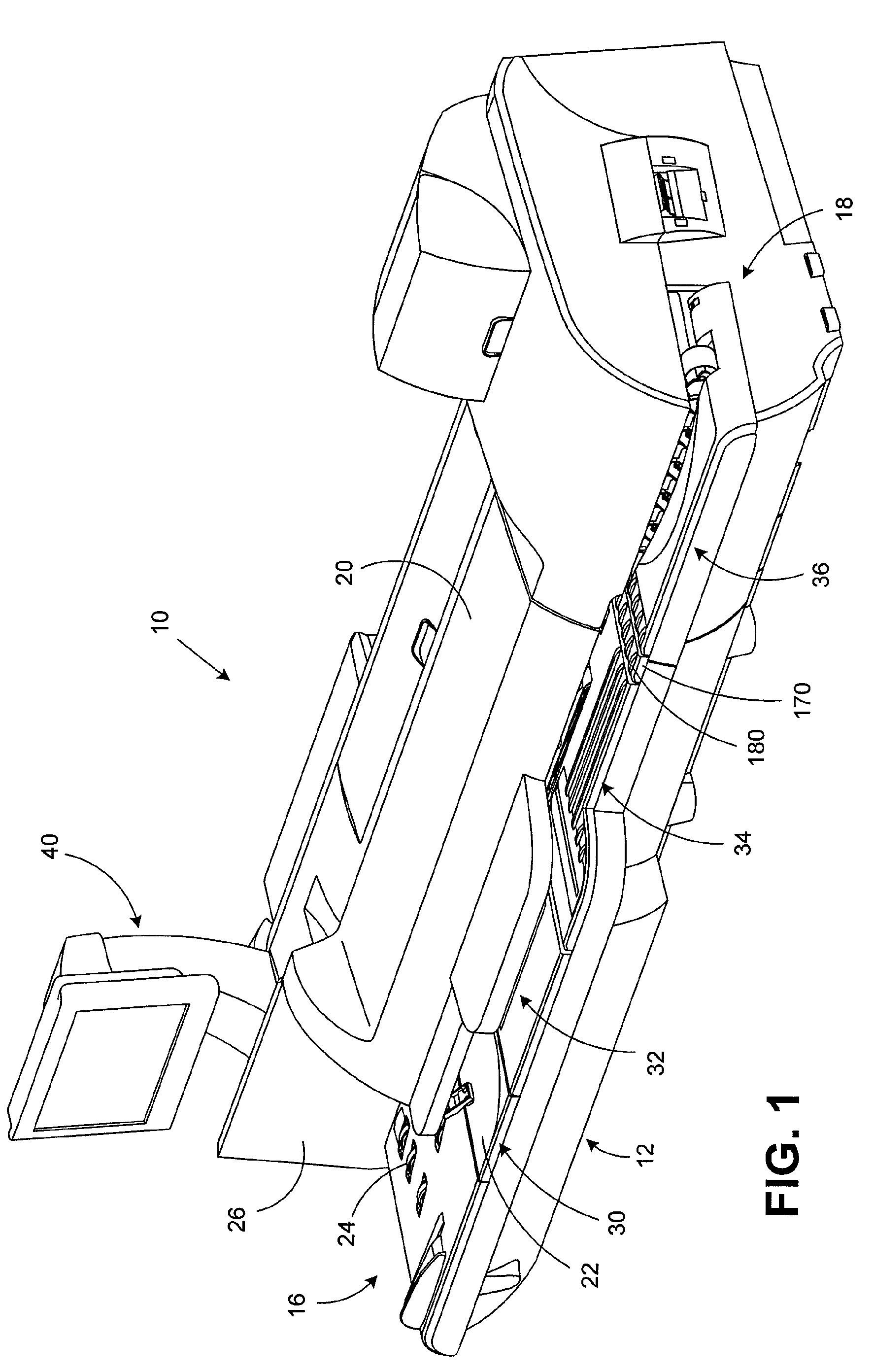
[0014]In describing the present invention, reference is made to the drawings, wherein there is seen in FIG. 1 an illustrative mail processing system in the form of a mailing machine 10 according to an embodiment of the present invention. Mailing machine 10 comprises a base unit, designated generally by the reference numeral 12, the base unit 12 having a mail piece input end, designated generally by the reference numeral 16, and a mail piece output end, designated generally by the reference numeral 18. One or more cover members 20 are pivotally mounted on the base 12 so as to move from the closed position shown in FIG. 1 to an open position (not shown) to expose various operating components and parts for service and / or repair as needed.

[0015]The base unit 12 further includes a horizontal feed deck 22 which extends substantially from the input end 16 to the output end 18. A plurality of nudger rollers 24 are suitably mounted under the feed deck 22 and project upwardly through openings...


PUM


Abstract

A mail processing system having a transport that reduces the amount of oscillation of the scale to allow for faster weighing of mail pieces is provided. A mailing machine includes a plurality of different modules through which mail pieces are fed by a transport system. A guide piece is provided in the transport path between the weighing module and the subsequent module, e.g., a printing module. The guide piece is structured such that forces imparted on the weighing platform of the weighing module by the trail edge of a mail piece being transported off of the weighing platform are reduced. Because of the reduction in this significant external force on the weighing platform, a faster weighing algorithm can be used on more mail pieces, thereby increasing the throughput of the mailing machine.

Description

FIELD OF THE INVENTION[0001]The invention disclosed herein relates generally to mail processing systems, and more particularly to a mail processing system having a transport mechanism with an integral scale that reduces the time required for weighing mail pieces.BACKGROUND OF THE INVENTION[0002]Mail processing systems for preparing mail pieces, e.g., stuffing envelopes, and / or printing postage indicia on envelopes and other forms of mail pieces have long been well known and have enjoyed considerable commercial success. There are many different types of mail processing systems, ranging from relatively small units that handle only one mail piece at a time, to large, multi-functional units that can process thousands of mail pieces per hour in a continuous stream operation. The larger mailing machines often include different modules that automate the processes of producing mail pieces, each of which performs a different task on the mail piece. Such modules could include, for example, a ...

Claims


Application Information

Patent Timeline
Patent Type & Authority Patents(United States)
IPC IPC(8): G01G19/414G01G21/00
CPCG01G19/002G07B17/00193G07B17/00467G07B2017/00701
Inventor ALLEN, ROBERT J.LYGA, THOMAS M.
Owner PITNEY BOWES INC
Learn More