
Apparatus, methods and computer programs for converting sound waves to electrical signals

a technology of electrical signals and apparatus, applied in the direction of diaphragm construction, frequency response correction, and semiconductor electrostatic transducers, can solve the problems of distorted output signal of microphones, and inability to accurately represent incident sound waves

Inactive Publication Date: 2012-05-08
NOKIA TECH OY
View PDF8 Cites 11 Cited by
  • Summary
  • Abstract
  • Description
  • Claims
  • Application Information

AI Technical Summary

Benefits of technology

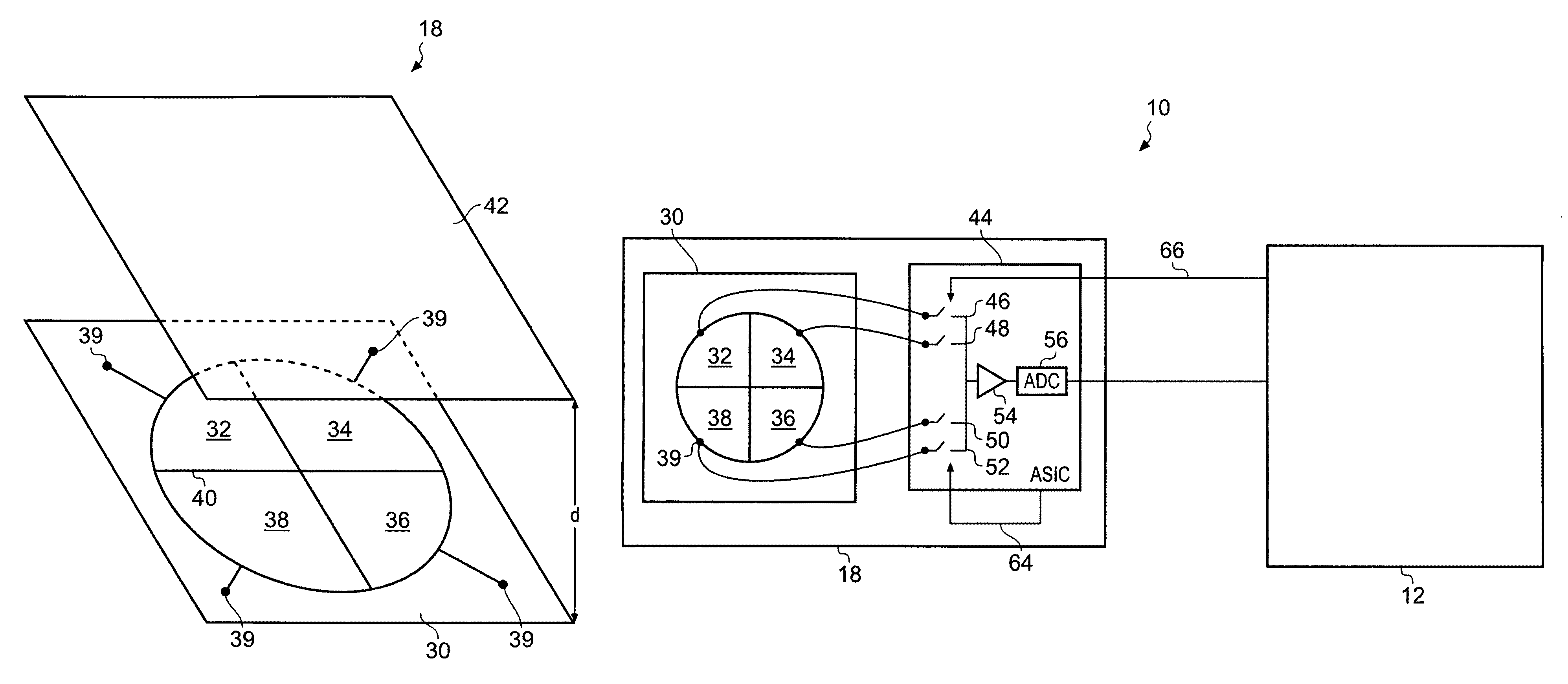
[0070]Embodiments of the present invention may provide an advantage in that they may dynamically select the sensitivity of the apparatus 18 and thereby improve the quality of a signal output from the apparatus 18. For example, if a device including the apparatus 18 is in a relatively noisy environment where the sound pressure level of the sound waves is high (greater than ninety decibels for example), the apparatus 18 may reduce the number of portions of the first member 30 connected to the amplifier 54 and thereby reduce distortion in the signal provided to the processor 12. Similarly, if a device including the apparatus 18 is in a relatively quiet environment where the sound pressure level of the sound waves is low (less than thirty decibels for example), the apparatus 18 may increase the number of portions of the first member 30 connected to the amplifier 54 and thereby increase the amplitude of the signal provided to the processor 12.

Problems solved by technology

If the sound pressure level of an incident sound wave is too high (for example, at a rock concert), the output signal from the microphone may be distorted.
Additionally, if the sound pressure level of an incident sound wave is too low, the output signal from the microphone may not be an accurate representation of the incident sound wave (that is, parts of the sound wave may be missing in the output signal).

Method used


Image

  • Apparatus, methods and computer programs for converting sound waves to electrical signals
  • Apparatus, methods and computer programs for converting sound waves to electrical signals
  • Apparatus, methods and computer programs for converting sound waves to electrical signals

Examples


Embodiment Construction

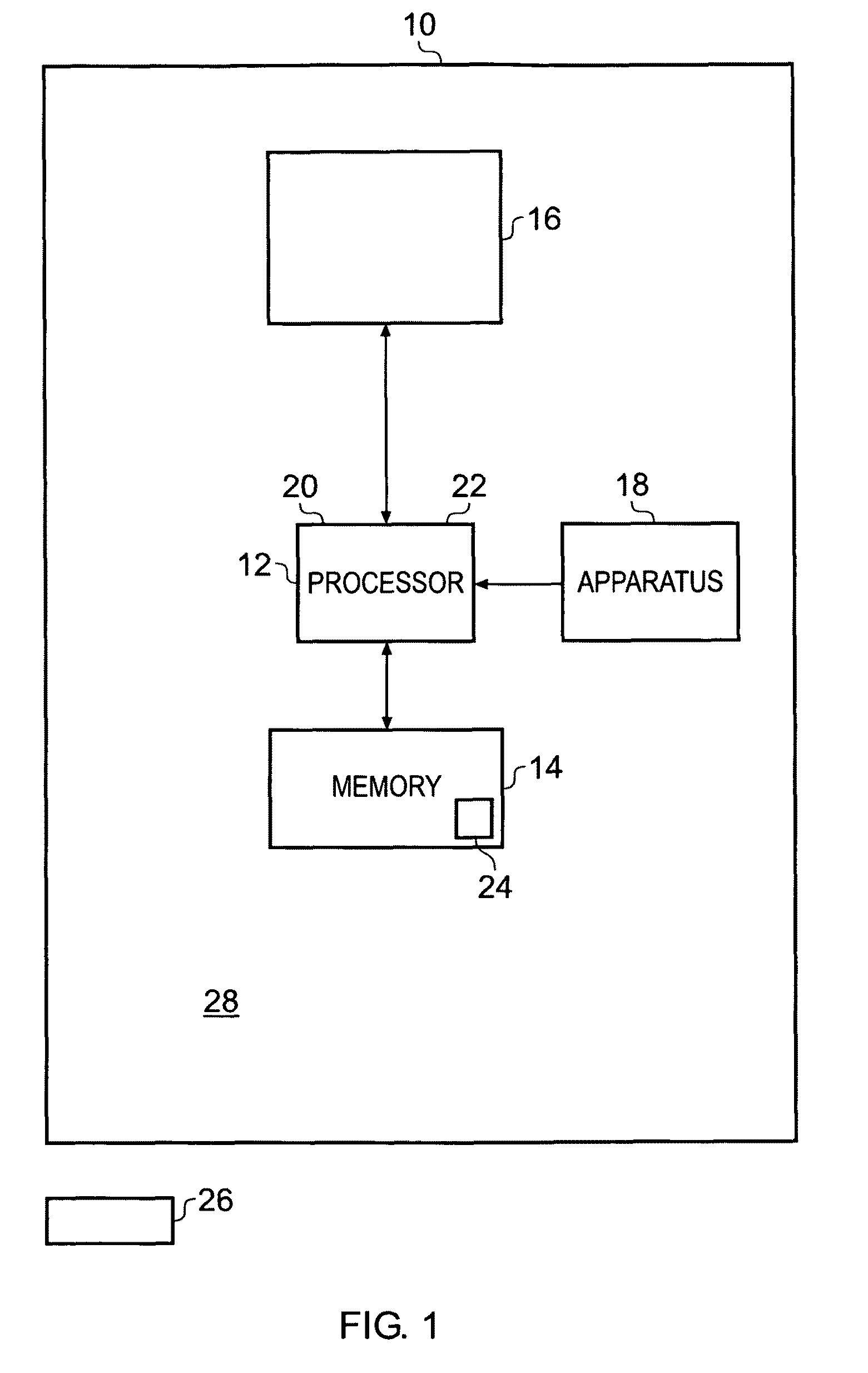
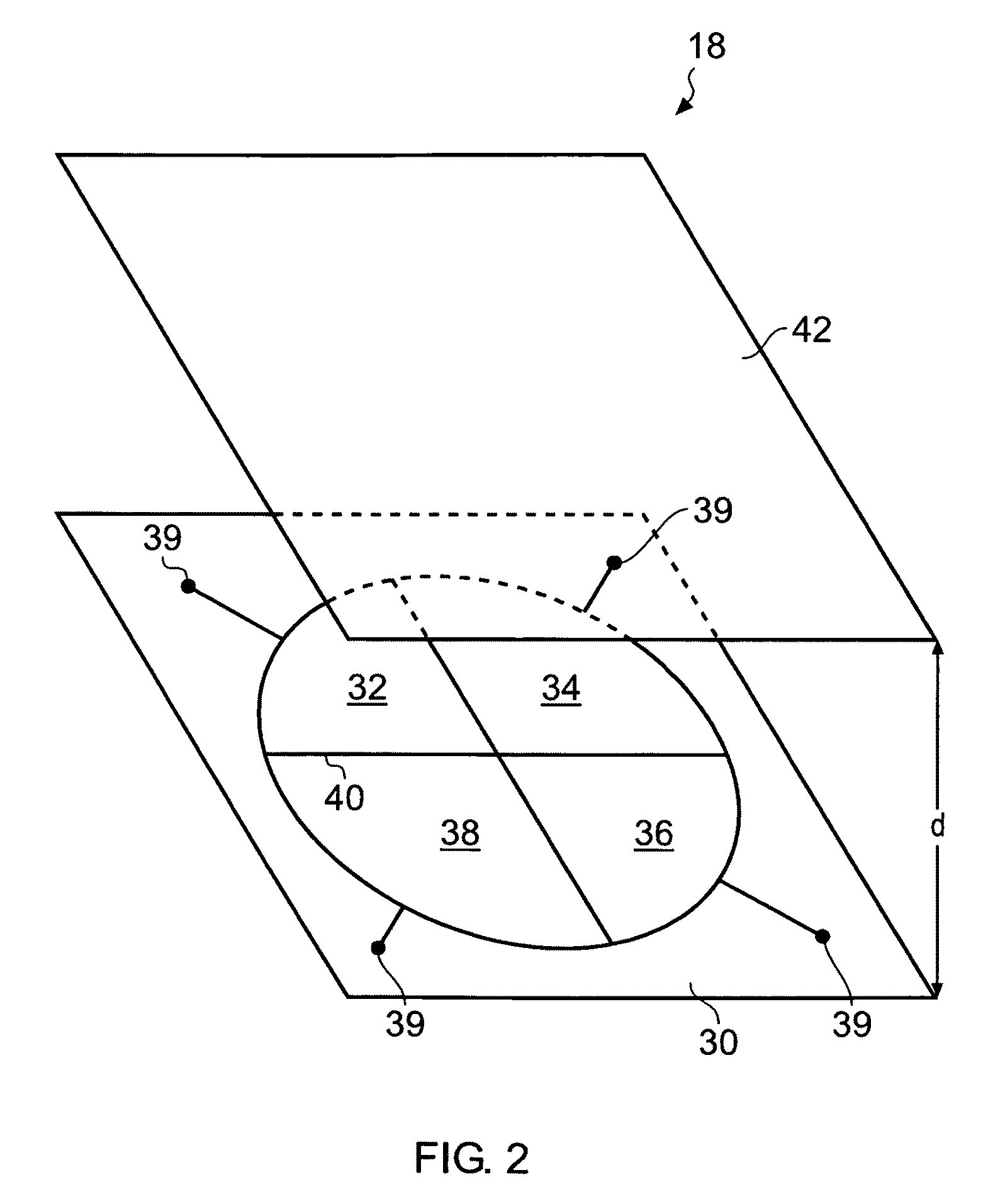
[0005]According to various, but not necessarily all, embodiments of the invention there is provided an apparatus comprising: a first member including a plurality of portions separated from one another by electrical insulator material; a second member configured to form capacitors with the plurality of portions of the first member; and wherein one of the first member and the second member are configured to vibrate in response to sound waves, and a first portion of the plurality of portions is configured to provide a first output signal representative of the sound waves and a second portion of the plurality of portions is configured to provide a second output signal representative of the sound waves.

[0006]The apparatus may be for converting sounds waves to electrical signals.

[0007]The second member may include a plurality of portions separated from one another by electrical insulator material.

[0008]The first portion may include a port for providing the first output signal representati...


PUM


Abstract

An apparatus comprising: a first member including a plurality of portions separated from one another by electrical insulator material; a second member configured to form capacitors with the plurality of portions of the first member; and wherein one of the first member and the second member are configured to vibrate in response to sound waves, and a first portion of the plurality of portions is configured to provide a first output signal representative of the sound waves and a second portion of the plurality of portions is configured to provide a second output signal representative of the sound waves.

Description

FIELD OF THE INVENTION[0001]Embodiments of the present invention relate to apparatus, methods and computer programs for converting sound waves to electrical signals. In particular, they relate to apparatus, methods and computer programs for converting sound waves to electrical signals in mobile cellular telephones.BACKGROUND TO THE INVENTION[0002]Devices such as mobile cellular telephones usually include a microphone for converting sound waves to electrical signals. For example, a user of such a device may speak into the microphone of the mobile cellular telephone to talk to a user of another mobile cellular telephone.[0003]Microphones for such devices are usually designed so that they provide an optimum output signal when the incident sound waves have a sound pressure level substantially equal to the sound pressure level of human speech. If the sound pressure level of an incident sound wave is too high (for example, at a rock concert), the output signal from the microphone may be d...

Claims


Application Information

Patent Timeline
Patent Type & Authority Patents(United States)
IPC IPC(8): H04R3/00H04R11/04
CPCH04R19/016H04R19/005H04R3/04H04R3/005H04R19/04H04R7/06
Inventor SUVANTO, MIKKO VELI AIMO
Owner NOKIA TECH OY
Learn More