
Superconducting cable line

a superconducting cable and cable technology, applied in the direction of superconducting magnets/coils, container discharge methods, domestic cooling apparatuses, etc., can solve the problems of reducing application, achieve the effect of reducing or substantially eliminating energy for cooling, reducing temperature differences, and effectively reducing heat intrusion into the cabl

Inactive Publication Date: 2012-05-08
SUMITOMO ELECTRIC IND LTD
View PDF16 Cites 4 Cited by
  • Summary
  • Abstract
  • Description
  • Claims
  • Application Information

AI Technical Summary

Benefits of technology

The present invention relates to a line for power supply using a superconducting cable, which decreases heat intrusion into the cable and increases the coefficient of performance (COP) as a whole line. The invention includes a heat insulation pipe for transporting liquid hydrogen and a superconducting cable housed in the heat insulation pipe for cooling with the refrigerant. The invention also includes a heat exchange means for cooling liquid hydrogen and rising the temperature of the refrigerant. The technical effect of the invention is to reduce energy for cooling the superconducting cable and liquid hydrogen, and to increase the COP of the whole line.

Problems solved by technology

Such a low COP is one of causes of a decreased application effect of a superconducting apparatus such as a superconducting cable.

Method used


Image

  • Superconducting cable line
  • Superconducting cable line
  • Superconducting cable line

Examples


example 1

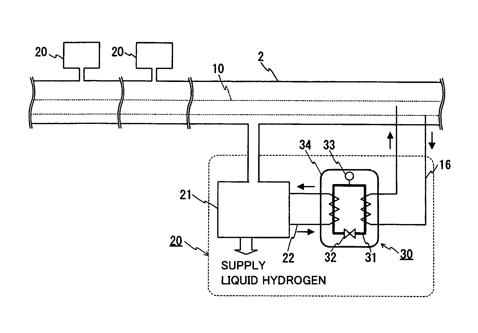
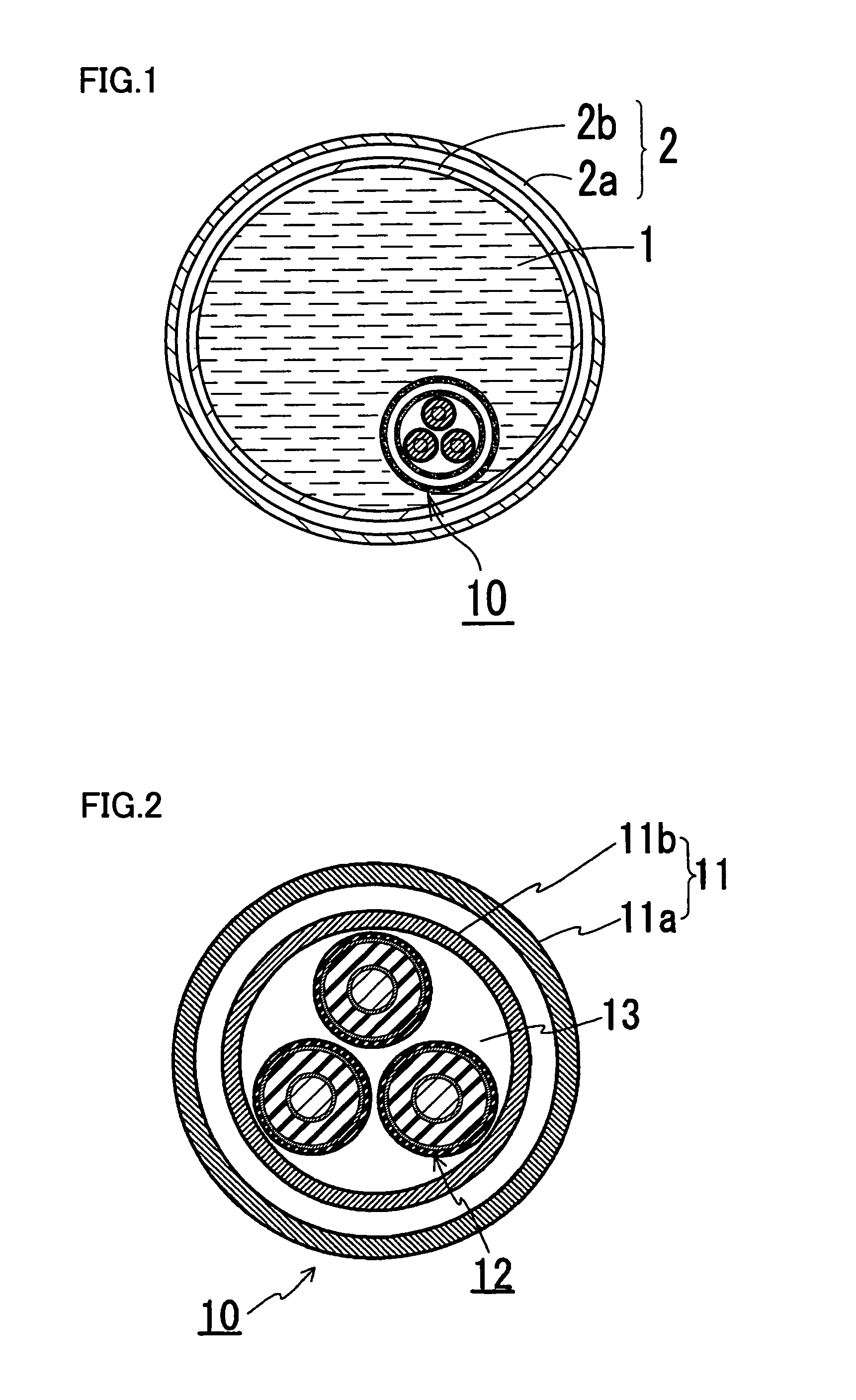
[0049]FIG. 1 is a schematic cross-sectional view of a construction of a superconducting cable line of the present invention. FIG. 2 is a schematic cross-sectional view of a construction of a portion near a superconducting cable in the superconducting cable line of the present invention. FIG. 3 is a schematic view of a construction in which the superconducting cable line of the present invention is constructed. The same characters in the drawings indicate the same portions. The superconducting cable line of the present invention includes a heat insulation pipe for a fluid 2 transporting liquid hydrogen 1, a superconducting cable 10 housed in heat insulation pipe for a fluid 2, and heat exchange means 30 for adjusting a temperature of liquid hydrogen 1 and a temperature of a refrigerant of the cable.

[0050]Superconducting cable 10 utilized in this example has a construction in which three cable cores 12 are stranded and housed in a heat insulation pipe for a cable 11, which constructio...

example 2

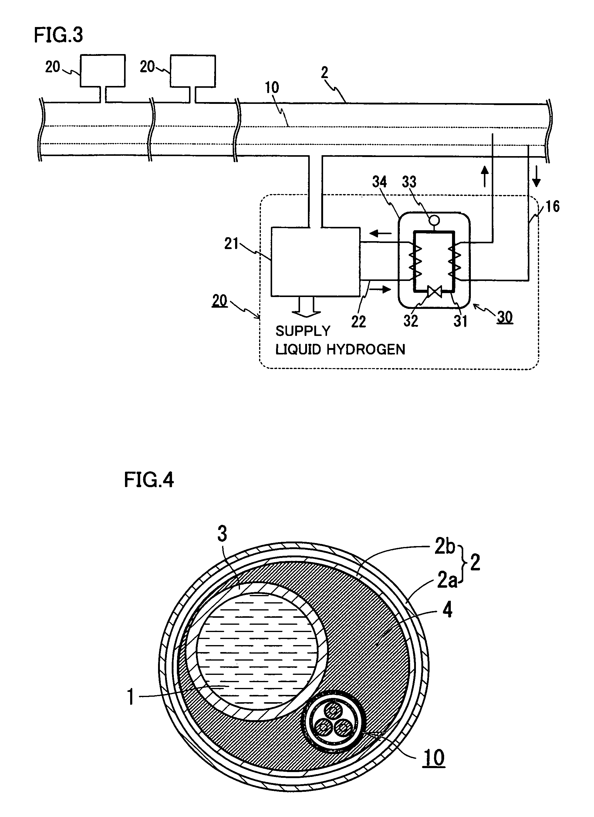
[0056]Though the superconducting cable was immersed in liquid hydrogen in example 1 described above, the superconducting cable may be housed in the heat insulation pipe for a fluid without being immersed in liquid hydrogen. As an example, a transportation passage for liquid hydrogen may be separately provided in the heat insulation pipe for a fluid. FIG. 4 is a schematic view of a construction of the superconducting cable line of the present invention including a transportation pipe for liquid hydrogen and a heat exchanger spacer inside the heat insulation pipe for a fluid, which is a schematic cross-sectional view of a construction of a portion near the cable. This superconducting cable line has a construction including a separate transportation pipe 3 for liquid hydrogen in internal pipe 2b of heat insulation pipe for a fluid 2. A heat exchanger spacer 4 having high heat conductivity is arranged in space enclosed with an inner periphery of internal pipe 2b, an outer periphery of t...


PUM

PropertyMeasurementUnit
cryogenic boiling pointaaaaaaaaaa
temperatureaaaaaaaaaa

Abstract

A superconducting cable line includes a heat insulation pipe for a fluid for transporting liquid hydrogen, a superconducting cable housed in the heat insulation pipe for a fluid, and heat exchange means for performing a heat exchange between liquid hydrogen and a refrigerant of the cable. The superconducting cable includes a cable core inside a heat insulation pipe for a cable and is housed in the heat insulation pipe for a fluid to form a low temperature environment around the cable and a double heat insulation structure including the heat insulation pipe. Therefore, since heat intrusion into the superconducting cable is reduced and the refrigerant is cooled with liquid hydrogen, the line can reduce energy for cooling the refrigerant.

Description

TECHNICAL FIELD[0001]The present invention relates to a line for power supply including a superconducting cable. More specifically, the present invention relates to a superconducting cable line which decreases heat intrusion into a superconducting cable to reduce energy for cooling a refrigerant used in the cable and can increase a coefficient of performance (COP) as a whole line.BACKGROUND ART[0002]A superconducting cable including a heat insulation pipe housing a cable core having a superconducting conductor layer has been conventionally known. Such a superconducting cable includes, for example, a single-core cable having a heat insulation pipe housing one cable core or a three-core cable housing three cable cores in a bundle. FIG. 7 is a cross-sectional view of a three-core superconducting cable for three-phase AC transmission. FIG. 8 is a cross-sectional view of each cable core 102. This superconducting cable 100 has a construction in which three stranded cable cores 102 are hou...

Claims


Application Information

Patent Timeline
Patent Type & Authority Patents(United States)
IPC IPC(8): H01B12/00
CPCH01B12/16Y02E40/647Y10T29/49014Y10S505/886Y10S505/888Y02E40/60H01B12/00
Inventor HIROSE, MASAYUKIYAMADA, YUICHI
Owner SUMITOMO ELECTRIC IND LTD
Learn More