
Automotive water heater

a water heater and motor technology, applied in the field of automotive water heaters, can solve the problems of affecting the service life of the water heater, so as to avoid the tripping of the power supply and ensure the stability of the electrical heating

Inactive Publication Date: 2012-05-01
WU CHIA HSIUNG
View PDF20 Cites 21 Cited by
  • Summary
  • Abstract
  • Description
  • Claims
  • Application Information

AI Technical Summary

Benefits of technology

"The present invention proposes to improve the effectiveness and benefit of an automottic water heater. The invention uses a laminated heating unit joined to a heat conducting surface of an exchange unit, which ensures good heat transmission efficiency. The heating unit can be easily replaced or repaired, and can be assembled in different sets. A buffer layer or device is installed between the heating unit and the heat conducting surface of the exchange bed to prevent damage to the heating unit. The heating unit uses a negative electrode connection to the exchange unit to avoid power supply tripping. The heating unit also uses a positive temperature coefficient ceramic resistance strip for stable electrical heating."

Problems solved by technology

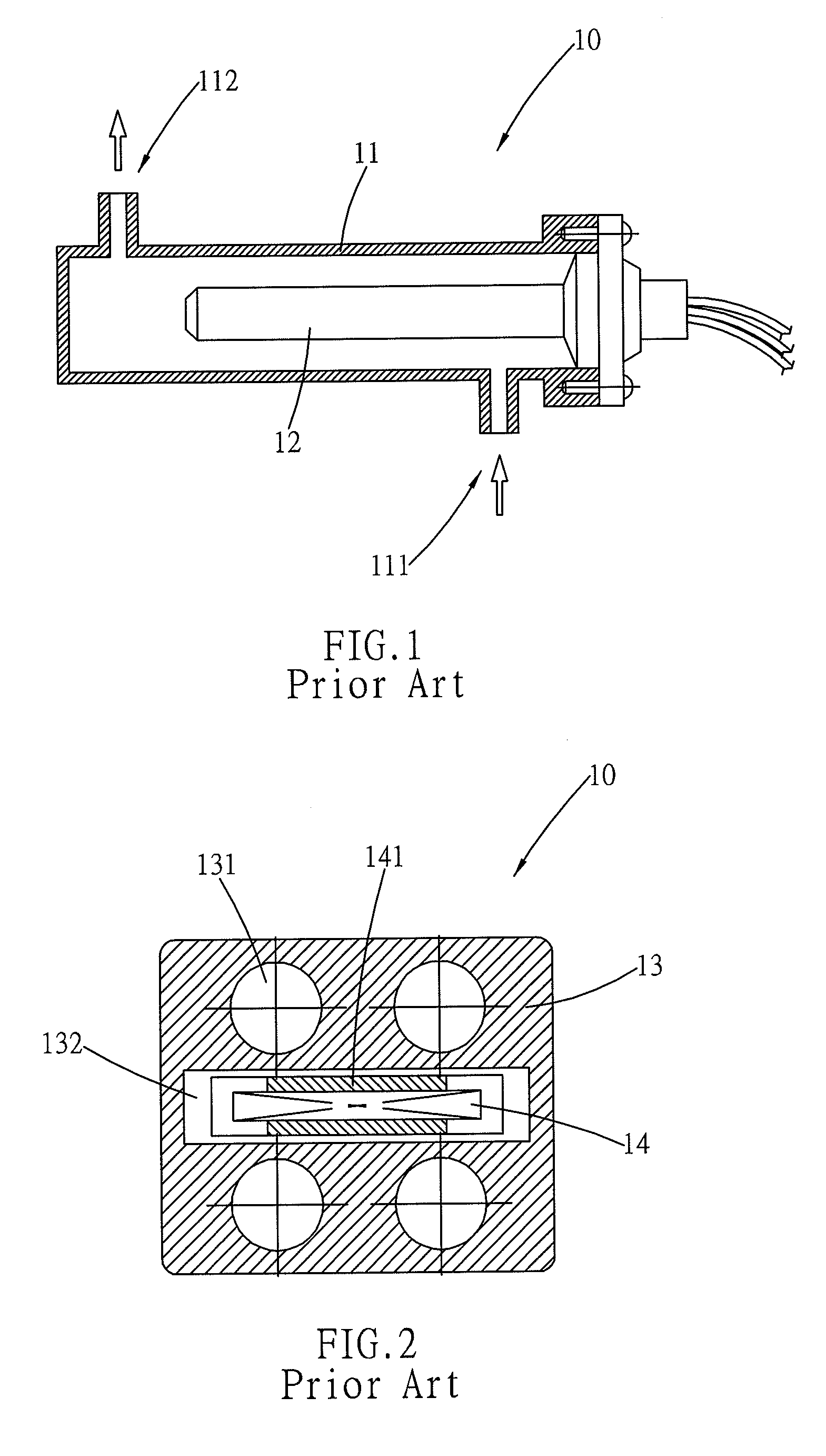
However, because the heating element 14 is the main body for cold and heat operation, thus, material quality of the heating element 14 is easily damaged.
Moreover, such a prior art configuration is difficult to repair when it breaks down, and involves a multitude of minor details during the assembly process.
Hence, it is common for the entire single heater 10 to be completely replaced, thereby resulting in meaningless waste and a burden on the environment.
The aforementioned prior art designs are unable to accommodate different power requirements by using a corresponding arrangement of heating elements.
Hence, during production, manufacturers must stock a multitude of heaters having different power specifications in order to rapidly supply client needs, thereby increasing inventory cost.
Moreover, such prior art designs disallow mass production of standard specifications.
Hence, the aforementioned shortcomings increase the total burden on production costs.

Method used


Image

  • Automotive water heater
  • Automotive water heater
  • Automotive water heater

Examples


Embodiment Construction

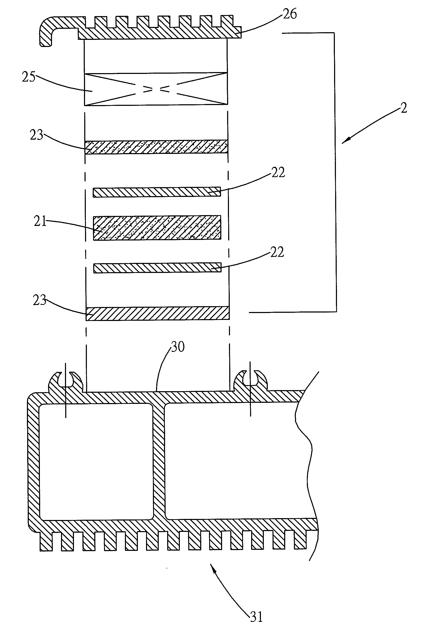
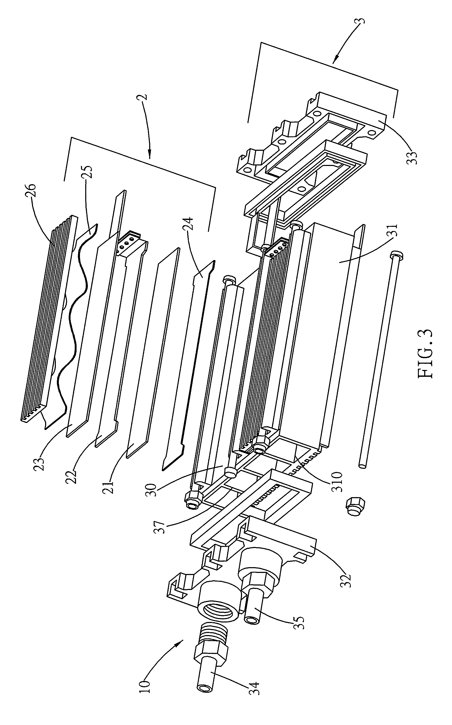
[0023]Referring to FIG. 3, which shows a heater 10 of the present invention primarily structured to comprise a laminated heating unit 2 face assembled to a heat exchange unit 3. The heating unit 2 conducts electric power through a heating strip 21 via a plate electrode 22, and an externally controlled switch operates working time. Electrical property of the plate electrode 22 is outwardly separated by an insulating plate 23, which is either provided with a heat conductivity or heat resisting property. In particular, the insulating plate 23 is located to a side of a sealing back plate 26, thereby actualizing a heat resisting property.

[0024]The heating strip 21 is fabricated from any electrothermal material, such as electric heating wire or a positive temperature coefficient ceramic resistance strip. The positive temperature coefficient ceramic resistance strip provides a constant temperature and automatic heat regulating function, which together with its intrinsic quality of being a ...


PUM


Abstract

An automotive water heater having application to a windshield of an automobile, which is able to produce hot water that can be sprinkled on the windshield to melt accumulated snow and frost, in which a water heater is mainly structured from a laminated assembled heating unit side joined to a heat conducting surface of an exchange bed. Heat quantity produced by the heating unit forms a heat balance function, which transfers the heat to the exchange bed, and water flow paths are defined interior of the exchange bed. The face joining of the laminated heating units is used to facilitate maintenance of component members and allow changing of the number of heating units assembled to the exchange bed, thereby providing choice to accommodate different power requirements.

Description

RELATED APPLICATION[0001]This application is a Continuation-In-Part of currently pending U.S. patent application Ser. No. 11 / 635,531 filed on Dec. 8, 2006 now abandoned.BACKGROUND OF THE INVENTION[0002](a) Field of the Invention[0003]The present invention relates to an automotive water heater, and more particularly to a water heater that has application to a windshield of an automobile, which is able to produce hot water that can be sprinkled on the windshield to melt snow and frost.[0004](b) Description of the Prior Art[0005]In frigid zones, after an automobile has been left in snowy weather, snow and frost covering the windshield blocks the line of vision in the automobile, and external force must be applied to remove the accumulated snow and frost. Methods for removing the snow and frost include the conventional methods of using an instrument to clear it away or hot water to melt and clean off the snow and frost, thereby avoiding scuffing the glass surface. Hence, in frigid zones...

Claims


Application Information

Patent Timeline
Patent Type & Authority Patents(United States)
IPC IPC(8): A47J31/00
CPCB60S1/487F24H1/009F24H1/142F24H9/1827
Inventor WU, CHIA-HSIUNG
Owner WU CHIA HSIUNG
Learn More