Receptacle structure, printed wiring board structure, and electronic device

a technology of printed wiring and electronic devices, applied in the direction of coupling device connections, sustainable manufacturing/processing, final product manufacturing, etc., can solve the problems of high cost of printing wiring boards, shoddy or inexpensive substrates cannot accommodate this very fine wiring pattern, and the need for higher quality or more expensive substrates to be used, so as to reduce the wiring area, fine wiring pattern, and the effect of high quality

Inactive Publication Date: 2012-04-24
PANASONIC CORP
View PDF24 Cites 10 Cited by
  • Summary
  • Abstract
  • Description
  • Claims
  • Application Information

AI Technical Summary

Benefits of technology

[0009]To reduce the wiring area located on the mounting face of the printed wiring board, the wires extending from one of the rear lands must pass between two of the front lands, thereby creating a very fine wiring pattern. However, it has been discovered that shoddy or inexpensive substrates can not accommodate this very fine wiring pattern. Instead, higher quality or more expensive substrates must be used, which, as a result, drives up the cost of manufacturing the printed wiring board.

Problems solved by technology

However, it has been discovered that shoddy or inexpensive substrates can not accommodate this very fine wiring pattern.
Instead, higher quality or more expensive substrates must be used, which, as a result, drives up the cost of manufacturing the printed wiring board.

Method used


Image

  • Receptacle structure, printed wiring board structure, and electronic device
  • Receptacle structure, printed wiring board structure, and electronic device
  • Receptacle structure, printed wiring board structure, and electronic device

Examples


Embodiment Construction

[0020]Embodiments of the present invention will now be explained with reference to the drawings. It will be apparent to those skilled in the art from this disclosure that the following descriptions of the embodiments are provided for illustration only and not for the purpose of limiting the present invention as defined by the appended claims and their equivalents. In the description of the drawings that follows, those components that are the same or similar are numbered the same or similarly. However, the drawings are just schematic, and the dimensional proportions and so forth may not always be the same as with an actual product. Therefore, all specific dimensions and so forth should be judged with the following description in mind. Naturally, the following encompasses portions for which the dimensional relations and proportions differ between the drawings.

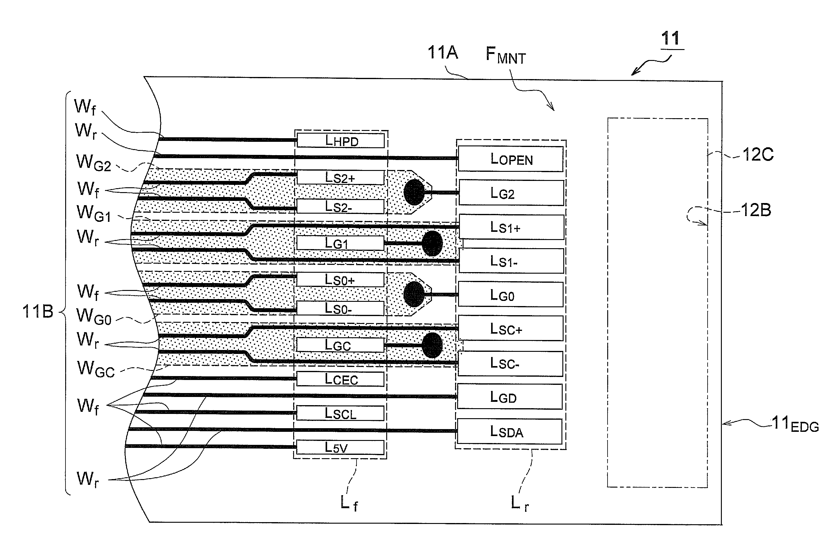
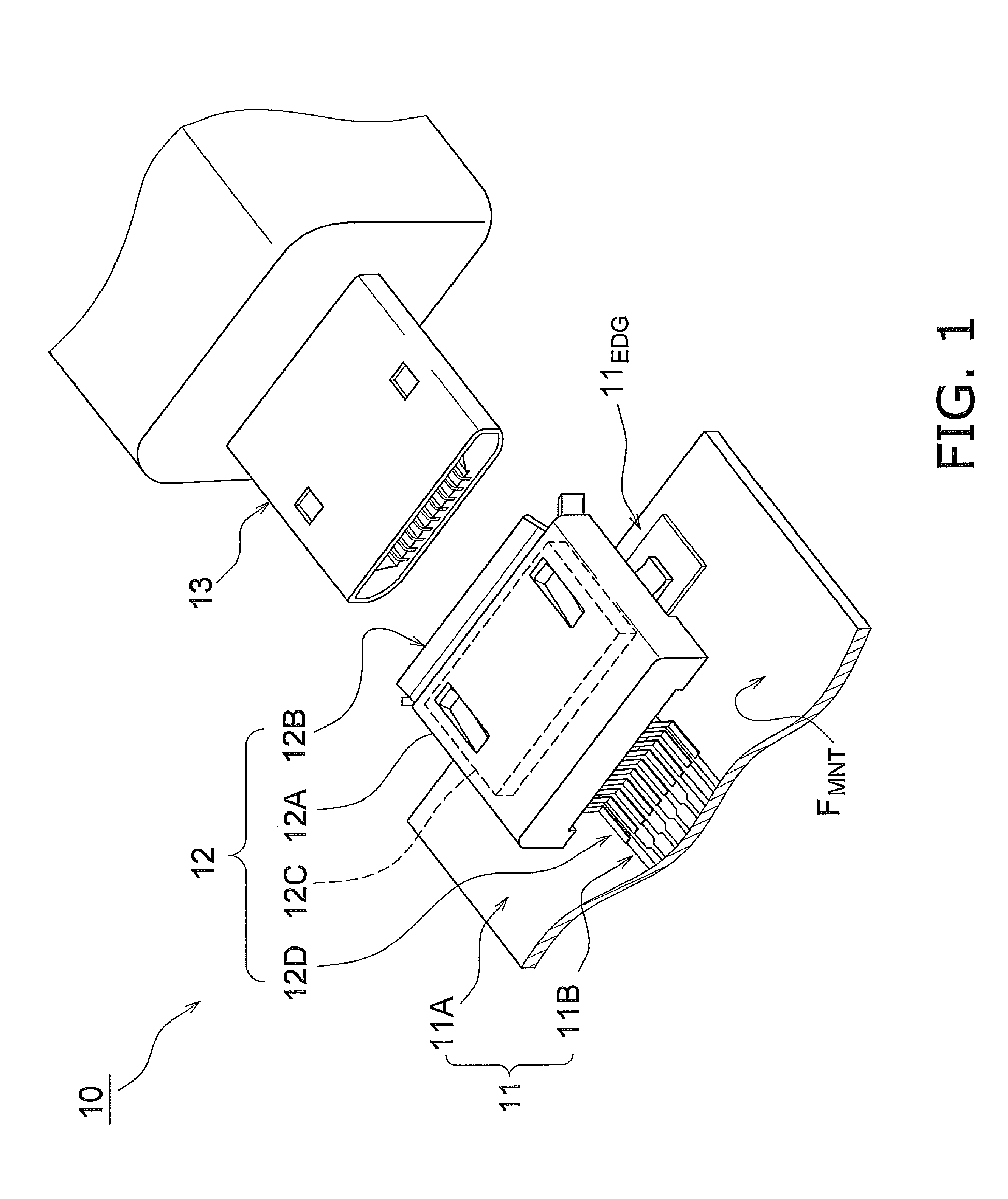
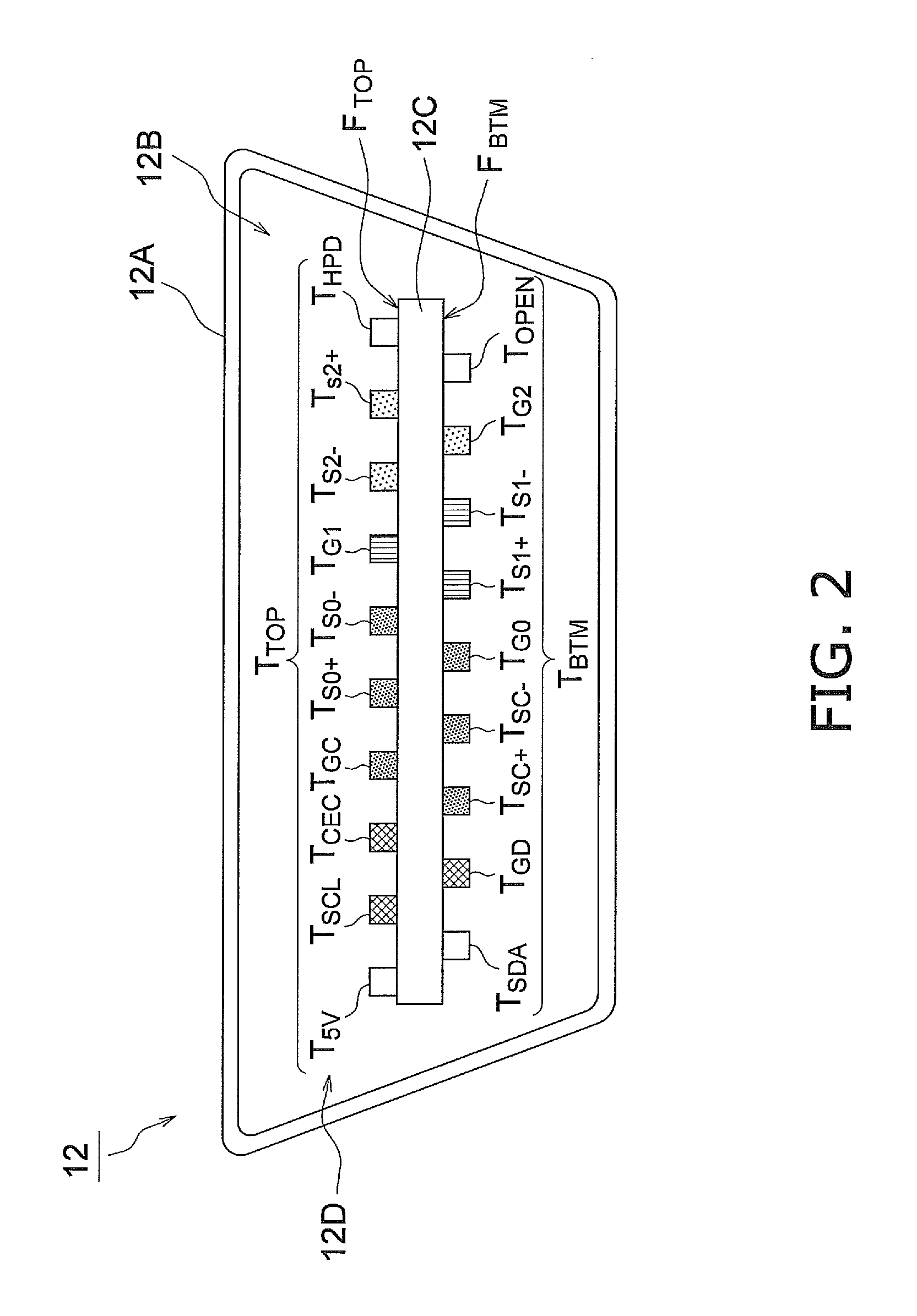
[0021]1: Configuration of Interface

[0022]The configuration of an interface pertaining to this embodiment will be described thro...


PUM


Abstract

A receptacle structure includes a housing structure, a terminal insulating board, a first terminal and a second terminal. The housing structure is configured to be mounted on a printed wiring board and to accommodate a plug. The terminal insulating board includes a top face and a bottom face that is opposite to the top face. The terminal insulating board is disposed inside the housing structure with the bottom face facing towards the printed wiring board. The first terminal is connected to the printed wiring board via the first rear connection part and to the terminal insulating board. The second terminal is connected to the printed wiring board via the first front connection part and to the terminal insulating board. The first front connection part has a width narrower than the first rear connection part and is connected to the printed wiring board away from the first rear connection part.

Description

CROSS-REFERENCE TO RELATED APPLICATIONS[0001]This application claims priority under 35 U.S.C. §119 to Japanese Patent Application No. 2010-033996 filed on Feb. 18, 2010. The entire disclosure of Japanese Patent Application No. 2010-033996 is hereby incorporated herein by reference.BACKGROUND[0002]1. Technical Field[0003]The present invention relates to a receptacle structure, a printed wiring board structure and an electronic device equipped with the receptacle structure and the printed wiring board structure.[0004]2. Background Information[0005]Recent years have witnessed the widespread application of technology whereby digital signals are sent at high speed between electronic devices (such as AV devices or portable devices) via an interface that conforms to the HDMI (High-Definition Multimedia Interface®) standard, the USB (Universal Serial Bus) standard, or the like. These interfaces are made up of a receptacle that is mounted on a mounting face of a printed wiring board, and a p...

Claims


Application Information

Patent Timeline
Patent Type & Authority Patents(United States)
IPC IPC(8): H01R12/00
CPCH01R12/724H01R43/16H05K1/111H01R13/6582H05K1/141H05K3/3426H05K2201/0373H05K2201/09709H05K2201/09727H05K2201/1034H05K2201/10757H05K2201/10818Y02P70/611Y02P70/50
Inventor MATSUBARA, RYOUMIMURA, SHOUICHIFUSAYASU, HIROTSUGUKUMOI, MASAFUMINAKAIE, TOSHIYUKI
Owner PANASONIC CORP
Why Eureka
Try Eureka