
Magnetic recording medium and production method thereof

a technology of magnetic recording medium and production method, which is applied in the field of magnetic recording medium, can solve the problems of reducing production efficiency, not being perfect, and increasing the chance of possible information reading error, and achieves excellent stability, weather resistance, and durability.

Active Publication Date: 2012-04-17
DIC CORPORATION
View PDF20 Cites 0 Cited by
  • Summary
  • Abstract
  • Description
  • Claims
  • Application Information

AI Technical Summary

Benefits of technology

The solution ensures stable and consistent reading outputs without fluctuations, maintains pattern stability over time, and enhances production efficiency by allowing for rapid pattern changes and improved design recognition.

Problems solved by technology

Consequently, the chance of possible information reading errors tends to be increased.
This method has a certain effect on reducing the output fluctuations due to the level-difference, but it is not perfect.
Furthermore, an additional coating step of filling the non-patterned area is required, which inevitably reduces the production efficiency.
Also, it is generally difficult to obtain both excellent sublimation and stability in sublime dyes.
Therefore, the formed pattern does not always have sufficient weather-resistant storage stability and stability over time.
Therefore, it is difficult to completely eliminate the level-difference of the fluorescent pattern.
Such a remaining level-difference causes reading output-fluctuations and deteriorates signals in quality.
However, the ink composition and the resin composition of the concealing layer have to be carefully selected to properly impregnate the fluorescent agent into the concealing layer.
The fluorescent pattern may highly possibly be blurred or fail to provide sufficient emission intensity as a result of slight changes in procedure.
Therefore, a limited selection of inks and resins and a limited degree of freedom in design are imposed.
Furthermore, in the prior art method of producing a pattern formed magnetic recording medium in which a pattern is formed on the magnetic-stripe part through the transfer step has the following inconvenience.
Therefore, when the pattern has to be modified after the patterned magnetic stripe-forming transferable laminate is completed, the pattern cannot be modified in a short time and the pattern-modification is a major cause of significantly delayed delivery and reduced performance.
When the pattern is formed on the magnetic recording layer of a magnetic recording medium as described above, the pattern often undergoes deteriorated signal properties or fails to fulfill the expected function as the sophisticated design or anti-counterfeit.
Furthermore, the prior art method of producing a pattern formed magnetic recording medium does not offer excellent production efficiency.Patent Document 1: Japanese Unexamined Patent Application, Publication No.

Method used


Image

  • Magnetic recording medium and production method thereof
  • Magnetic recording medium and production method thereof
  • Magnetic recording medium and production method thereof

Examples


examples

[0124]The present invention is described in more detail hereafter using examples and comparative examples. However, the present invention is not limited to these examples. The term “parts” means “parts by mass” hereafter.

[0125]Examples using chromatic dyes or fluorescent dyes as the coloring agent in the pattern-forming agent are described hereafter.

[0126]The following temporal carrier base film and paints are used in the examples and comparative examples.

A. Temporal Carrier Base Film: Polyethylene Terephthalate Film Having a Thickness of 24 μm;

B. Preparation of the Paint for the Pattern-Forming Agent Anti-Diffusion Layer (Also Serving as a Protective Layer)

[0127]

cellulose acetate resin 8 parts(“L-20” produced by Daicel Chemical Industries; Tg: 187° C.)cellulose acetate propionate resin 2 parts(“CAP-504-0.2” produced by Eastman Chemical; Tg: 159° C.)acetone25 partsethyl acetate25 partstoluene20 partscyclohexanone20 partspolyisocyanate 4 parts(“Hardener No. 50 (active ingredients: 50...

example 1

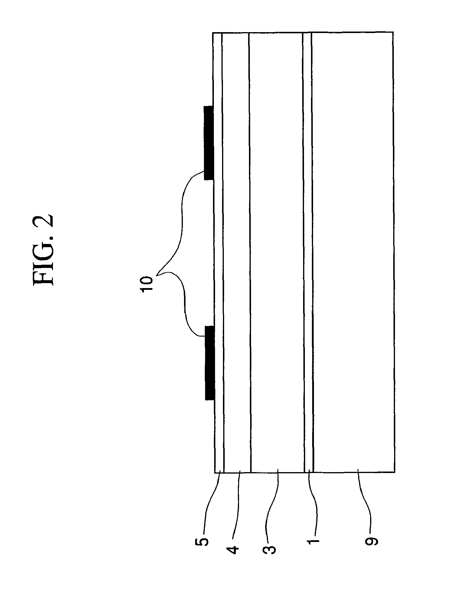
[0150]A polyethylene terephthalate film having a thickness of 24 μm was used as the temporal carrier base. The above described paints for a pattern-forming agent anti-diffusion layer, colored layer, magnetic recording layer, and heat-sensitive adhesive layer were applied and dried on one surface of the film in this order using a reverse coater to form a pattern-forming agent anti-diffusion layer, colored layer, magnetic recording layer, and heat-sensitive adhesive layer, respectively. The pattern-forming agent anti-diffusion layer had a dry thickness of 1 μm; the colored layer, 4 μm; the magnetic recording layer, 9 μm; and the heat-sensitive adhesive layer, 1.5 μm.

[0151]A pattern was printed on the heat-sensitive adhesive layer of the transferable material prepared above by way of the gravure printing using the pattern-forming ink [A] as shown in FIG. 6, such that the portion of the printed pattern had a thickness of 1 μm. It was then allowed to stand in a constant temperature room ...

example 2

[0153]A magnetic card was produced in the same manner as Example 1 except that the pattern-forming ink in the pattern printing of Example 1 was replaced with the pattern-forming ink [B].


PUM

PropertyMeasurementUnit
thicknessaaaaaaaaaa
thicknessaaaaaaaaaa
thicknessaaaaaaaaaa

Abstract

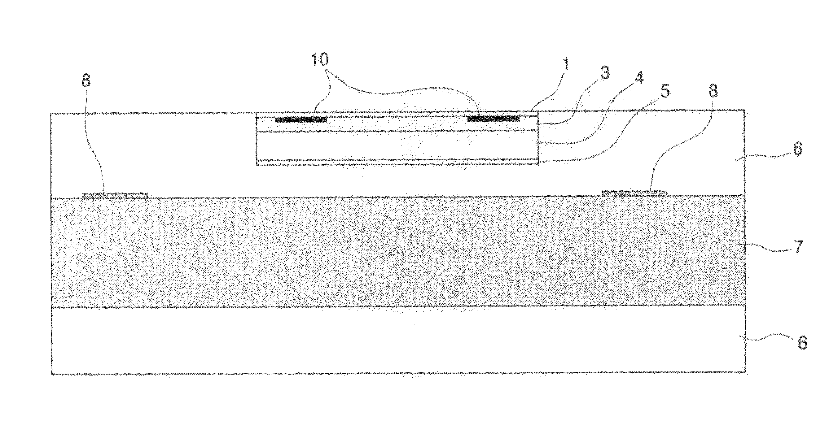
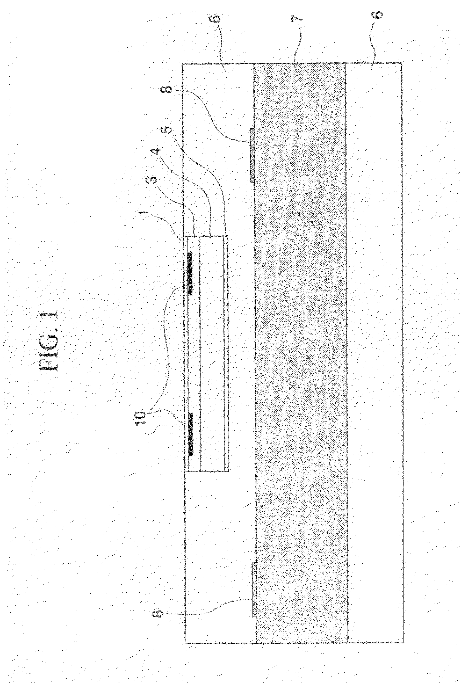
The magnetic recording medium of the present invention has a pattern formed using a pattern-forming agent in a laminate of multiple layers including a base material and a magnetic recoding layer, wherein the pattern is recognized on the surface of the laminate opposite to the base material, and the pattern-forming agent is distributed through the thickness of the laminate, wherein a region between the center of the magnetic recording layer and a magnetic recording-reading side of the laminate has an area having a density gradient of the pattern-forming agent which gradually declines in the direction from the center of the magnetic recording layer to the magnetic recording-reading side.

Description

TECHNICAL FIELD[0001]The present invention relates to a magnetic recording medium formed by laminating multiple layers including a base material and a magnetic recording layer and having a pattern recognized on the magnetic reading side of the magnetic recording layer, a method of producing the magnetic recording medium, and a transferable laminate used in the method of producing the magnetic recording medium. The present invention particularly relates to a card type magnetic recording medium formed by laminating layers including a magnetic recording layer on a card base material, such as credit cards and bank cards, and has on the magnetic stripe part a pattern recognized on the magnetic reading side, a method of producing the magnetic recording medium, and a transferable laminate used in the method of producing the magnetic recording medium.BACKGROUND ART[0002]Recently, various patterns are formed on various magnetic recording media for practical and design purposes.[0003]It is pa...

Claims


Application Information

Patent Timeline
Patent Type & Authority Patents(United States)
IPC IPC(8): G11B3/74G06K19/06B42D25/45G11B5/80G11B5/84
CPCG06K19/06196G11B5/70G11B5/80B42D25/45G06K19/06G11B5/84
Inventor YAMAZAKI, YOSHIKAZUYANO, DAISUKE
Owner DIC CORPORATION
Learn More