
Memory register having an integrated delay-locked loop

a delay-locked loop and register technology, applied in the field of memory applications, can solve the problems of delay between the clock edge, adversely affecting performance, introducing delays and errors into the signals, etc., and achieve the effect of improving the timing budg

Active Publication Date: 2012-04-03
INTEGRATED DEVICE TECH INC
View PDF11 Cites 1 Cited by
  • Summary
  • Abstract
  • Description
  • Claims
  • Application Information

AI Technical Summary

Benefits of technology

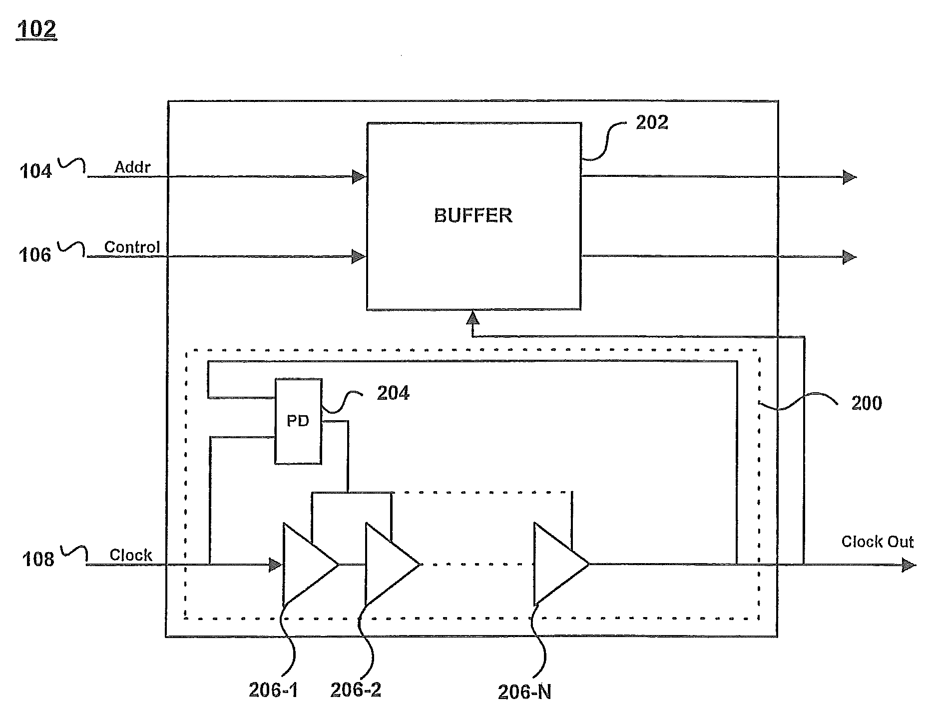
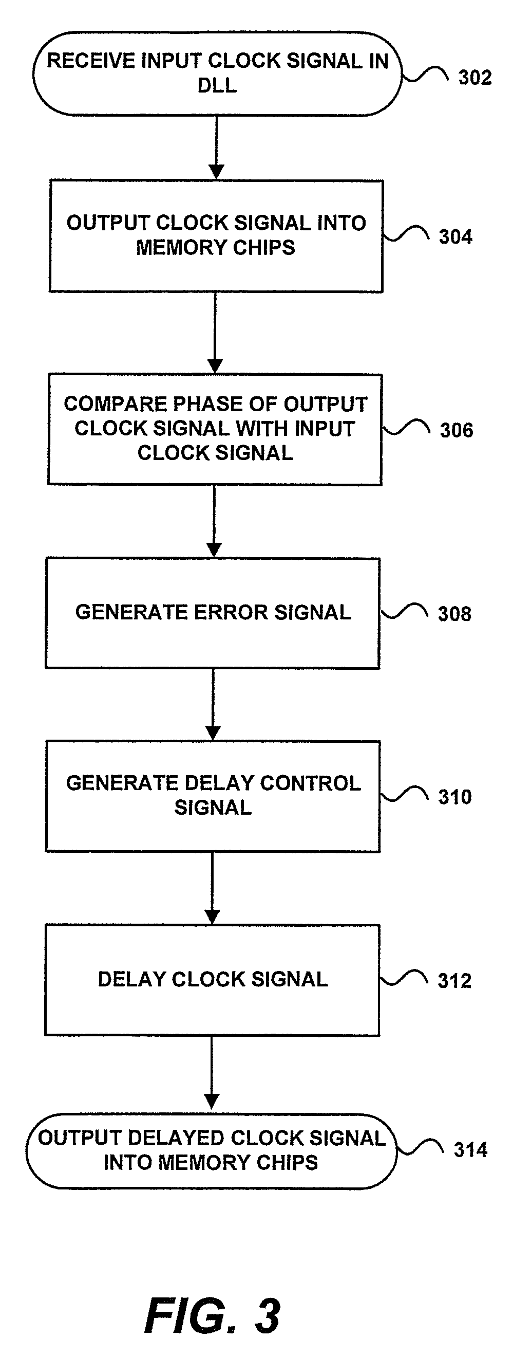
[0009]In accordance with aspects of the present invention, there is further provided a method for improving timing budgets in a registered dual in-line memory module (RDIMM) having a register which receives an input clock signal, the method comprising: providing a delay-locked loop in the register; receiving the input clock signal in the delay-locked loop; outputting an output clock signal from the delay-locked loop; comparing a phase of the output clock signal to a phase of the input clock signal; generating an error signal based on the comparison; integrating the error signal to generate a delay control signal; and delaying the output clock signal by a predetermined amount based on the control signal.

Problems solved by technology

However, adding a register to a DIMM package often adds a delay between the clock edge and the output swing, introducing delays and errors into the signals being transmitted to the memory chips.
For example, adding a register to a DIMM package may introduce dynamic phase offset and jitter, both of which affect the timing margins of the DIMM, and thus adversely affect performance.
Although the PLL is able to eliminate the errors, it also introduces additional delays into the signals, which also affect the performance of the DIMM.
The PLL also does not allow for tuning the register to vary the skew of the output signals.
Moreover, the voltage-controlled oscillator of the PLL increases power requirements for the DIMM, and introduces additional dynamic phase offset and jitter into the signal.

Method used


Image

  • Memory register having an integrated delay-locked loop
  • Memory register having an integrated delay-locked loop
  • Memory register having an integrated delay-locked loop

Examples


Embodiment Construction

[0015]In the following description specific details are set forth describing certain embodiments of the invention. It will be apparent, however, to one skilled in the art that the present invention may be practiced without some or all of these specific details. The specific embodiments presented are meant to be illustrative of the present invention, but not limiting. One skilled in the art may realize other material that, although not specifically described herein, is within the scope and spirit of this disclosure.

[0016]FIG. 1 illustrates a memory device 100 consistent with the present invention. In accordance with aspects of the present invention, memory device 100 may be a registered dual in-line memory module (RDIMM) package 100. Consistent with the present invention, RDIMM 100 may be a random access memory device in a processing system including a processor, such as, for example, a computer system.

[0017]RDIMM package 100 includes individual memory chips 101-1 through 101-N, coup...


PUM


Abstract

A memory device is provided. The memory device includes a plurality of memory chips coupled in series, and a register serially coupled to the memory chips. The register includes an integrated delay-locked loop. The memory device may be included in a processing system. Moreover, a method for improving timing budgets in a registered dual in-line memory module (RDIMM) may be implemented using the memory device having a register with an integrated delay-locked loop.

Description

TECHNICAL FIELD[0001]The present invention is related to memory applications and, in particular, to a register for a memory device, the register having an integrated delay-locked loop.DISCUSSION OF RELATED ART[0002]Dual In-Line Memory Modules (DIMMs) have become the industry standard for supplying random access memory (RAM) for computer applications. Each DIMM is typically a printed circuit board that includes a number of individual RAM chips. The RAM chips can be any memory chips, for example dynamic RAM (DRAM) chips or synchronous RAM (SRAM) chips. In some cases, the DIMM functions as a double data rate DIMM (DDR DIMM) where data is received both on the rising edge of the clock signal and on the falling edge of the clock signal.[0003]As the demand for memory density increases, DIMM packages that contain a higher density of RAM chips become important. One such DIMM package is a registered DIMM package (RDIMM). An RDIMM package includes one or more registers. The registers typically...

Claims


Application Information

Patent Timeline
Patent Type & Authority Patents(United States)
IPC IPC(8): G06F1/12
CPCG06F13/40G11C5/04G11C7/222
Inventor SMOLKA, JOHN
Owner INTEGRATED DEVICE TECH INC
Learn More