
Nonwoven fabric

a nonwoven fabric and fabric technology, applied in the field of nonwoven fabrics, can solve the problems of increasing the density of heat sealed areas, poor quick penetration characteristics of predefined liquids, and increasing the manufacturing steps of nonwoven fabrics or the method of manufacturing nonwoven fabrics described, and achieve the effect of rapid transfer

Inactive Publication Date: 2012-03-27
UNI CHARM CORP
View PDF67 Cites 68 Cited by
  • Summary
  • Abstract
  • Description
  • Claims
  • Application Information

AI Technical Summary

Benefits of technology

The present invention provides a nonwoven fabric that allows for rapid transfer of a predefined liquid, while adjusting the density and sparsity of the fabric. The fabric is formed by jetting a fluid consisting mainly of gaseous matter to a fiber web, and the nonjetted areas have a lower fiber density and density than the jetted areas. The nonwoven fabric can be used in various applications such as absorbent materials, and the technical effects include improved liquid transfer, reduced thickness, and improved softness.

Problems solved by technology

In other words, manufacturing steps of the nonwoven fabrics or the method for manufacturing the nonwoven fabrics described in JP-A No. 3587831 are complicated because a number of fiber layers having different shapes are needed to form irregularities in fiber webs.
This increases the density of the heat sealed areas, and the resultant film exhibits poor quick penetration characteristics of a predefined liquid, such as excretory substance, in that area.
Furthermore, it is difficult for the predefined liquid to be rapidly transferred because the periphery of the concave portions is consolidated or formed into a film by heat embossing.
For this reason, if a large quantity of the predefined liquid is being absorbed at a single moment, or if pressure is added to the nonwoven fabric, liquid may easily overflow from the concave portion.

Method used


Image

  • Nonwoven fabric
  • Nonwoven fabric
  • Nonwoven fabric

Examples


first embodiment

1. First Embodiment

[0061]The nonwoven fabric of the present invention according to the first embodiment will be explained while referring to FIGS. 2 to 5.

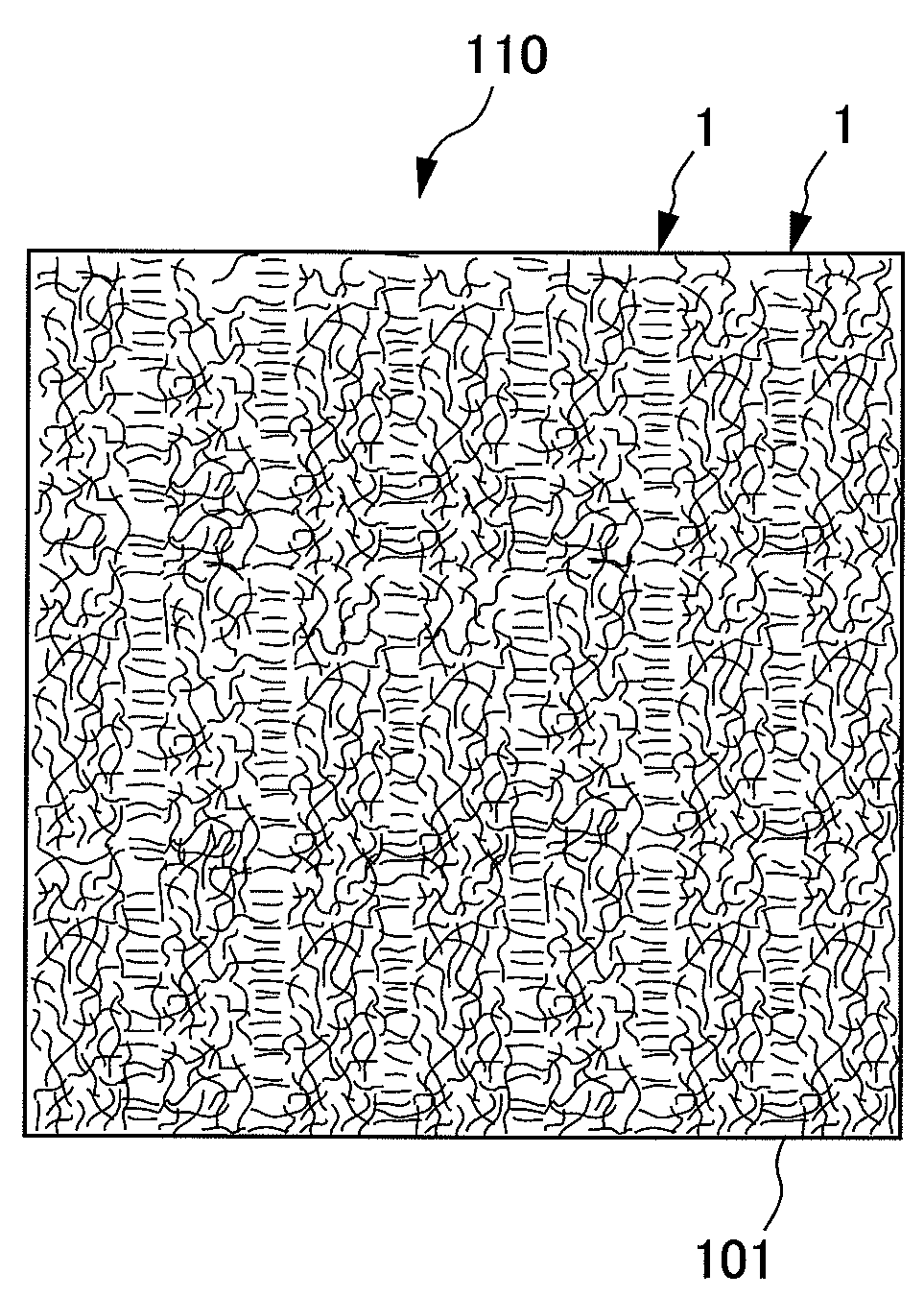
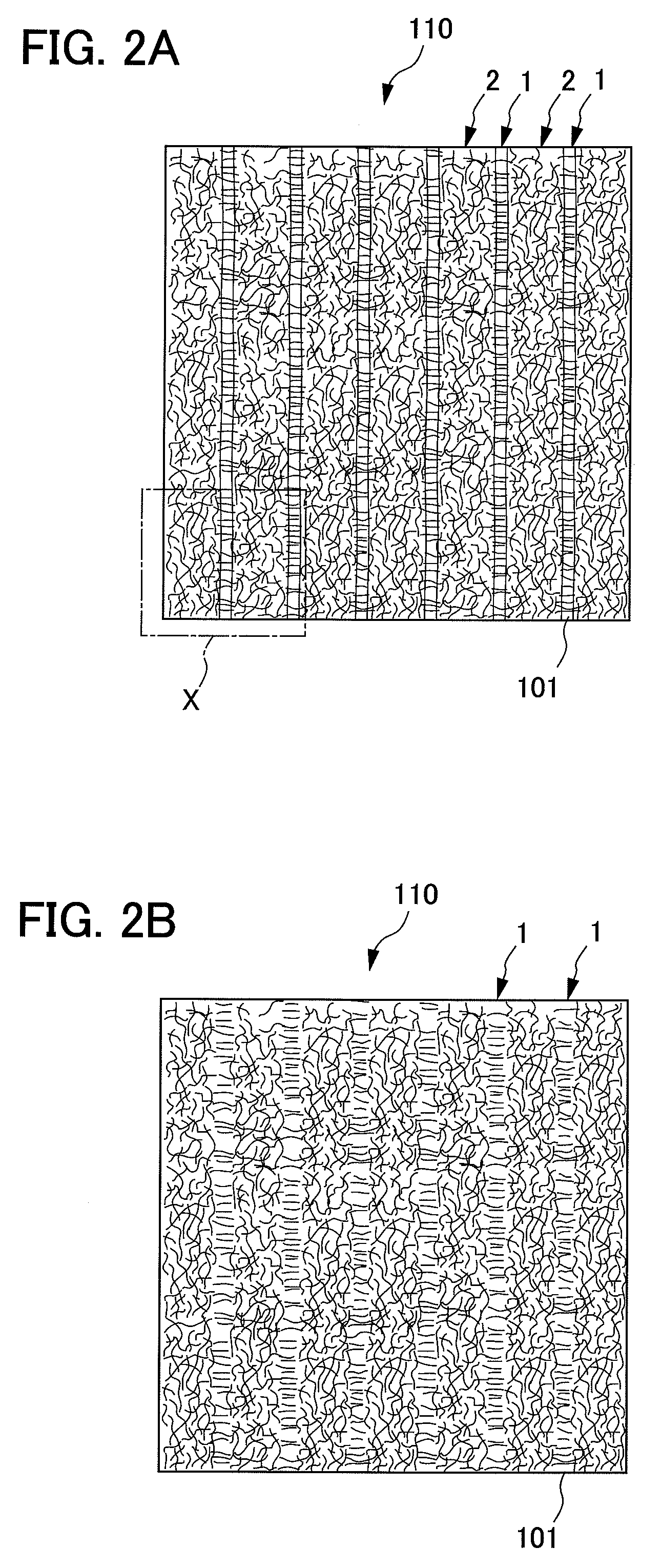
[0062]The nonwoven fabric 110 according to the first embodiment is a nonwoven fabric formed by jetting a fluid, consisting mainly of gaseous matter, into a fiber aggregate. A groove portion 1, which is an injected area to which the fluid, consisting mainly of gaseous matter, is jetted, and a convex portion 2, which is a nonjetted area to which the fluid, consisting mainly of gaseous matter, is not jetted, are formed. Furthermore, the nonwoven fabric 110 is a nonwoven fabric which has been adjusted so as the fiber density of the groove portion 1 to less than the fiber density of the convex portion 2.

1.1. Shape

[0063]In the nonwoven fabric 110 according to the first embodiment, a number of groove portions 1 are formed in parallel with each other at approximately regular intervals on one side of the nonwoven fabric 110 as shown in FIGS...

second embodiment

2.1. Second Embodiment

[0136]The nonwoven fabric of the present invention according to the second embodiment will be explained referring to FIG. 10.

2.1.1. Shape

[0137]The nonwoven fabric 114 according to the second embodiment is a nonwoven fabric having substantially flat surfaces on both sides as shown in FIG. 10. And areas of different fiber orientation are formed in predefined areas in the nonwoven fabric. The explanation below will focus on points which differ from the first embodiment.

2.1.2. Fiber Orientation

[0138]A number of areas which differ in the content of longitudinally oriented fibers are formed in the nonwoven fabric 114 as shown in FIG. 10. Examples of the areas which differ in the content of longitudinally oriented fibers include longitudinally oriented portions 13 where the content of the longitudinally oriented fibers is the greatest in the nonwoven fabric 114, center portions 12 where the content of the longitudinally oriented fibers is less than that of the longitu...

third embodiment

2.2. Third Embodiment

[0151]The nonwoven fabric of the present invention according to the third embodiment will be explained referring to FIGS. 11 and 12.

2.2.1. Nonwoven Fabric

[0152]The nonwoven fabric 116 according to the third embodiment differs from the nonwoven fabric as described in the first embodiment in having alternate roughness so that the entire nonwoven fabric 116 is crossed in the longitudinal direction. The nonwoven fabric 116 according to the third embodiment will be explained focusing on the points differing from the first embodiment.

[0153]The nonwoven fabric 116 according to the third embodiment is formed so as for the entire nonwoven fabric 116 to be corrugated in the longitudinal direction as machine direction.

2.2.2. Manufacturing Method

[0154]The method for manufacturing the nonwoven fabric 116 according to the third embodiment is similar to the method described in the first embodiment except for the embodiment of the net-like support member 260 as a breathable sup...


PUM

PropertyMeasurementUnit
densityaaaaaaaaaa
densityaaaaaaaaaa
temperatureaaaaaaaaaa

Abstract

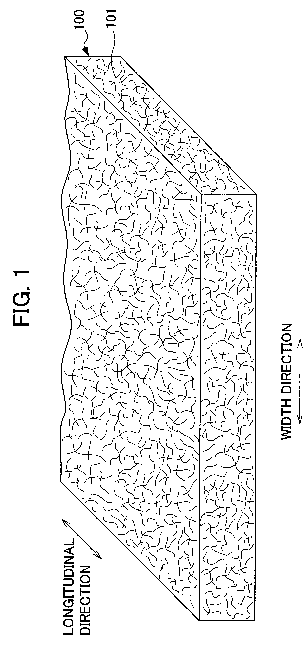
It is an objective of the present invention to provide a nonwoven fabric prepared so as to be able to rapidly transfer a predefined liquid. The nonwoven fabric is formed by jetting a fluid, which consists mainly of gaseous matter, to a fiber web 100 supported from beneath by a predefined breathable support member, from an upper surface side in order to move fibers in the fiber web 100. A number of groove portions 1 and a number of convex portions 2 are formed on a jetted area of the nonwoven fabric in the direction in which the area is extended, and the fiber density of the groove portions 1 is less than the fiber density of the convex portions 2.

Description

[0001]This application is based on and claims the benefit of priority from Japanese Patent Application No. 2006-174505, filed on Jun. 23, 2006 and from Japanese Patent Application No. 2006-270106, filed on Sep. 29, 2006, the content of which are incorporated herein by reference.BACKGROUND OF THE INVENTION[0002]1. Field of the Invention[0003]The present invention relates to nonwoven fabrics.[0004]2. Related Art[0005]Nonwoven fabrics have been used in a wide variety of fields including sanitary materials such as diapers and sanitary napkins, cleaning products such as cleaning wipers and medical supplies such as masks. Nonwoven fabrics are used in various fields, as described above, and it is necessary for nonwoven fabrics to be produced so as to have characteristics and structures suitable for use in each product application.[0006]Nonwoven fabrics are formed, for example, by forming fiber layers (fiber webs) by using either a dry method or a wet method, and binding the fibers that are...

Claims


Application Information

Patent Timeline
Patent Type & Authority Patents(United States)
IPC IPC(8): D04H3/10D04H1/70
CPCD04H1/42Y10T428/24992Y10T442/689Y10T442/696Y10T442/608Y10T442/60D04H1/76D04H1/732
Inventor NODA, YUKIISHIKAWA, HIDEYUKIMIZUTANI, SATOSHIKIMURA, AKIHIRO
Owner UNI CHARM CORP
Learn More