
On die thermal sensor

a technology of thermal sensors and on-die heat sinks, which is applied in the direction of heat measurement, instruments, testing circuits, etc., can solve the problems of data vanishing, consuming refresh power, and defect in the semiconductor uni

Active Publication Date: 2012-03-20
SK HYNIX INC
View PDF27 Cites 16 Cited by
  • Summary
  • Abstract
  • Description
  • Claims
  • Application Information

AI Technical Summary

Benefits of technology

[0039]Embodiments of the present invention are directed to an on die thermal sensor (ODTS) for correctly updating temperature information regardless of an operation mode of a dynamic random access memory (DRAM) by updating the temperature information of a semiconductor device according to a refresh period.

Problems solved by technology

However, since there occurs a leakage current due to a PN junction of a metal oxide semiconductor (MOS) transistor, the stored initial charge may be discharged and, thus, the data may vanish.
Due to the refresh operation, refresh power is consumed.
In case of a battery operated system, which requires lower power consumption, reducing power consumption is very important and is a critical issue.
The generated heat may cause a defect in the semiconductor unit.
As a result, a bandwidth efficiency of the data input and output through the input / output pins is deteriorated.
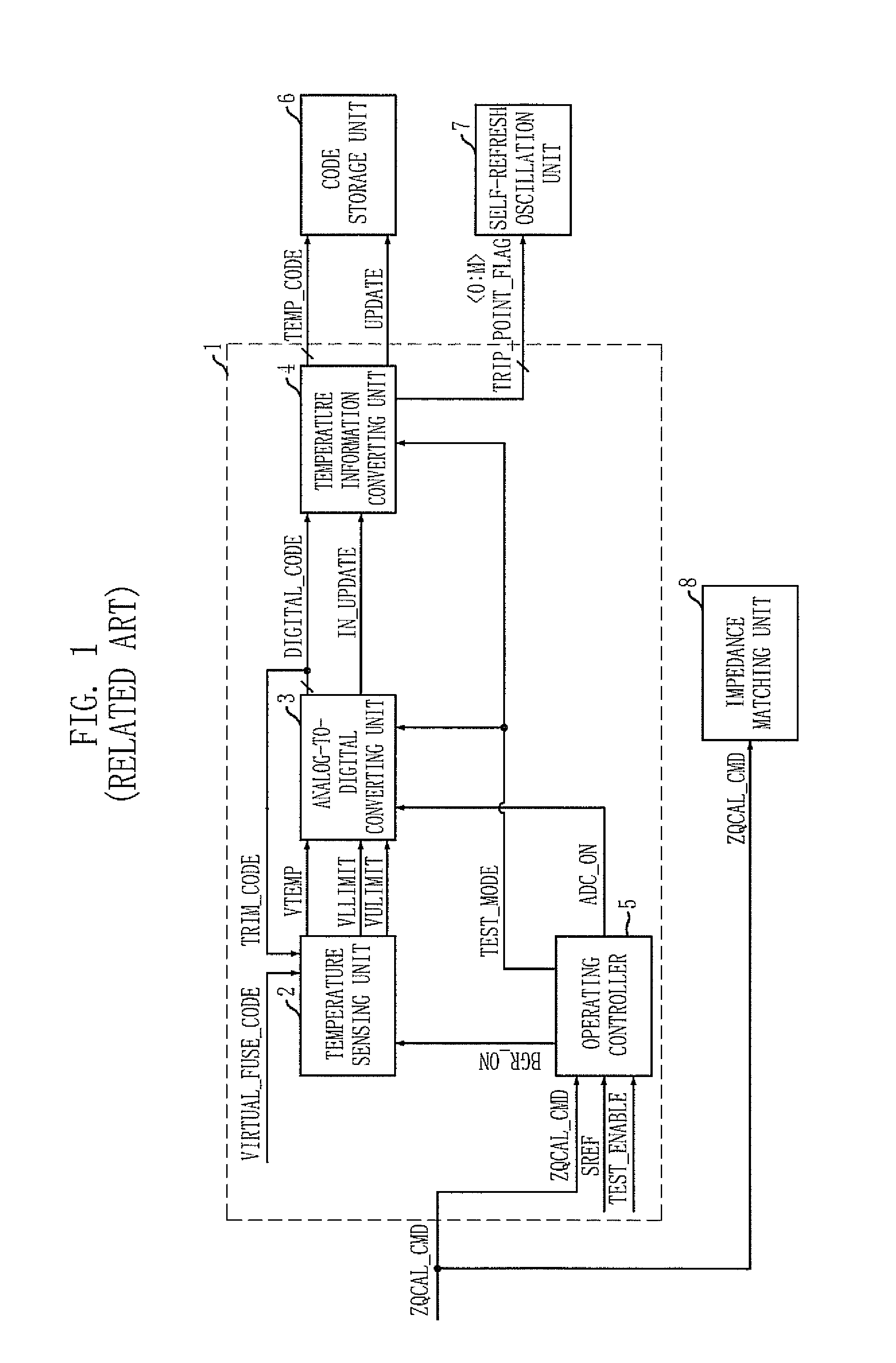
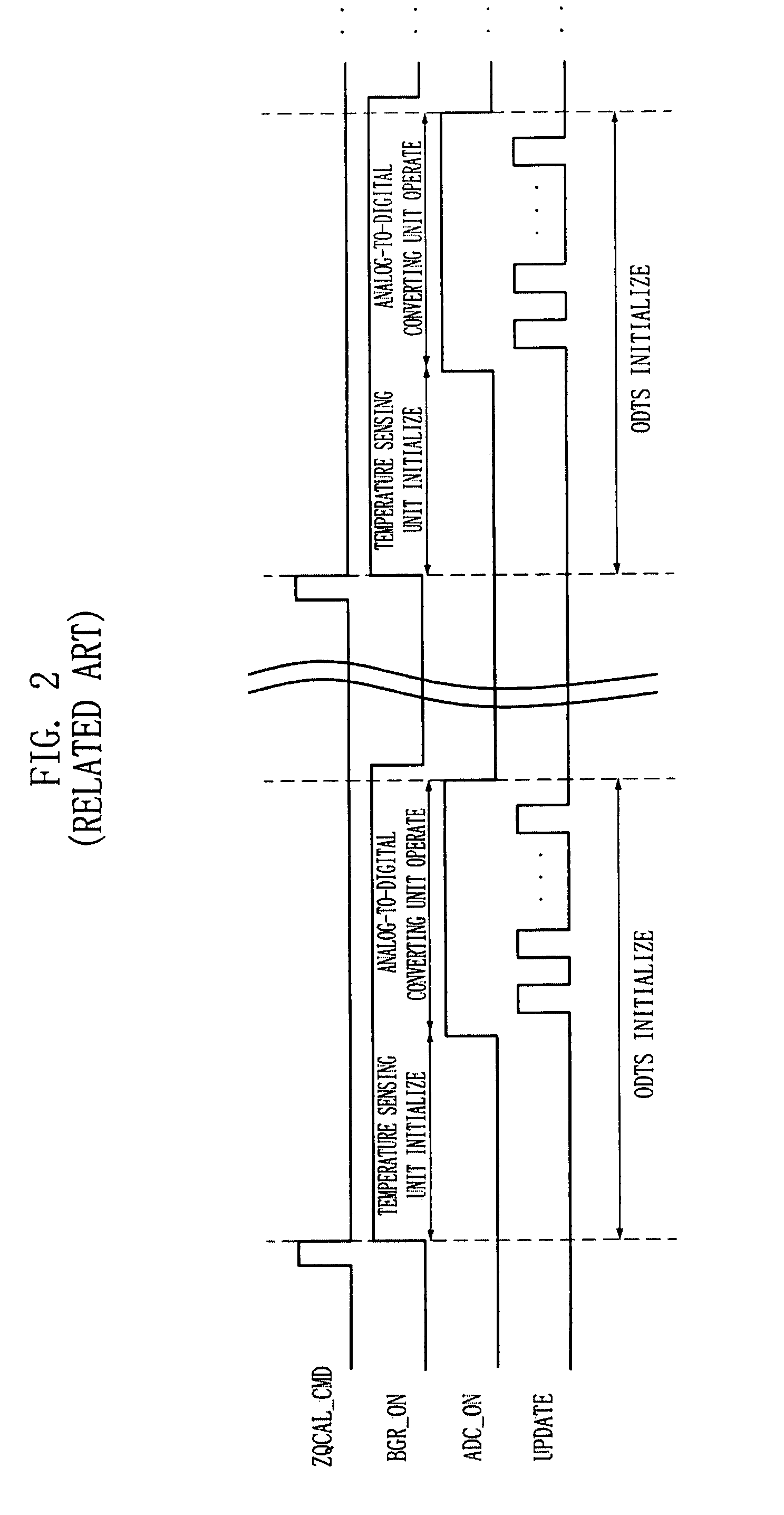
However, it is difficult for the conventional ODTS 1 to optimize each of the update period of the temperature information of the ODTS 1 and the input period of the impedance matching command ZQCAL_CMD because the conventional ODTS 1 updates the temperature information in response to the impedance matching command ZQCAL_CMD.
As a result, the conventional ODTS 1 is difficult to perform an efficient operation.

Method used


Image

  • On die thermal sensor
  • On die thermal sensor
  • On die thermal sensor

Examples


Embodiment Construction

[0051]It is an object of the present invention to provide an on die thermal sensor (ODTS) for updating temperature information according to a refresh period.

[0052]Hereinafter, the ODTS in accordance with the present invention will be described in detail referring to the accompanying drawings.

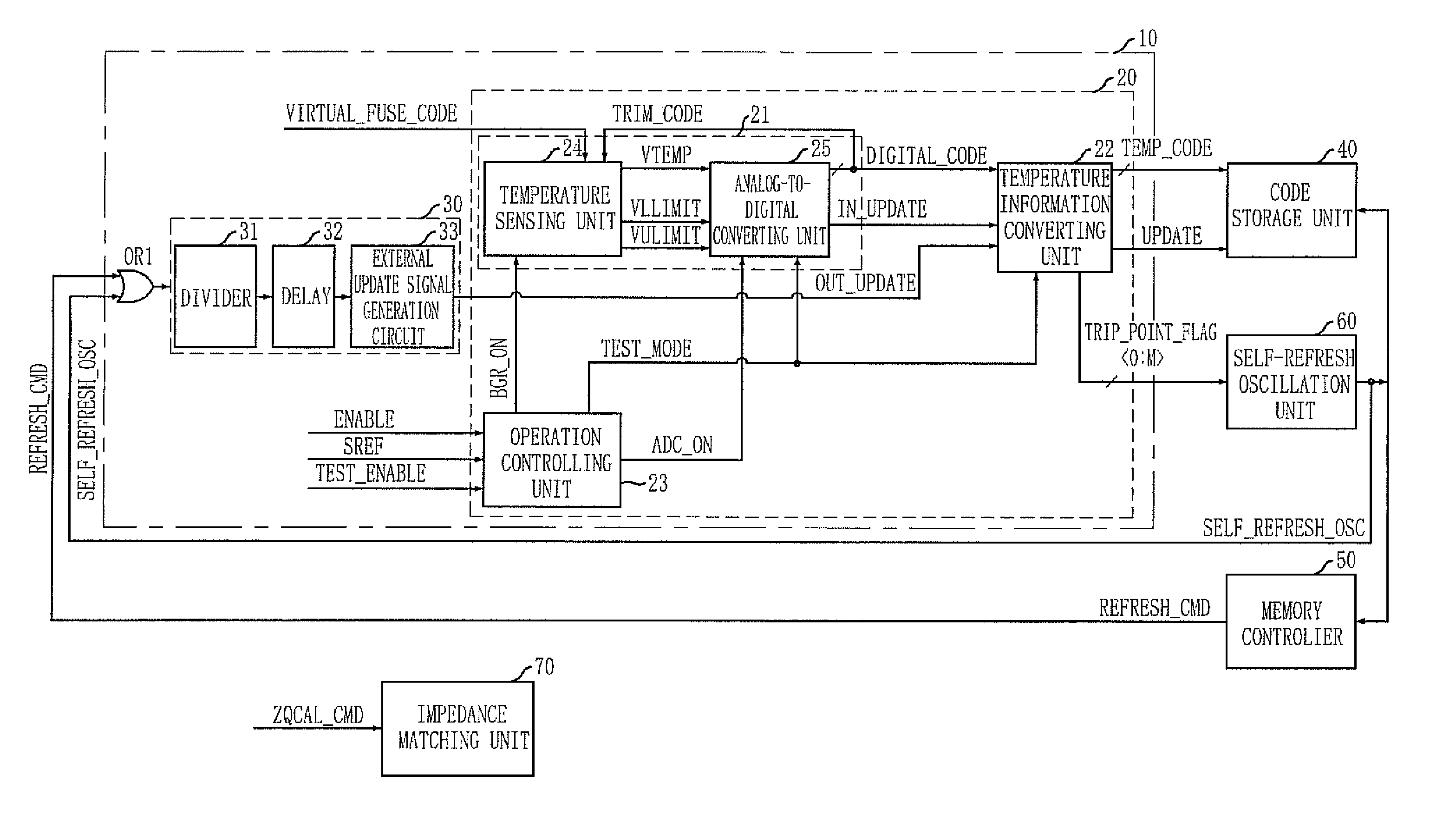
[0053]FIG. 3 is a block diagram of an ODTS for use in a semiconductor device in accordance with an embodiment of the present invention.

[0054]The ODTS of the present invention includes a temperature information output unit 10 which generates temperature information by measuring an internal temperature of the semiconductor device, and updates the temperature information according to a refresh period.

[0055]In detail, the temperature information output unit 10 includes a temperature information code generation unit 20 and an external update signal output unit 30.

[0056]The temperature information code generation unit 20 measures the internal temperature of the semiconductor device to generate a tempe...


PUM

PropertyMeasurementUnit
temperatureaaaaaaaaaa

Abstract

An on die thermal sensor (ODTS) for use in a semiconductor device includes a temperature information output unit for measuring an internal temperature of the semiconductor device to generate a temperature information code having temperature information, and updating the temperature information code according to a refresh period.

Description

CROSS-REFERENCE TO RELATED APPLICATIONS[0001]The present invention claims priority of Korean patent application number 10-2006-0095179, filed on Sep. 28, 2006, which is incorporated by reference in its entirety.BACKGROUND OF THE INVENTION[0002]The present invention relates to updating temperature information of an on die thermal sensor (ODTS), and more particularly, to a temperature information output unit for updating temperature information of a semiconductor device according to a refresh period.[0003]A dynamic random access memory (DRAM) cell includes a transistor for operating as a switch and a capacitor for storing a charge, i.e., data. According to whether the capacitor stores the charge, i.e., whether a terminal voltage of the capacitor is high or low, a logic level of the data is determined as a high level or a low level.[0004]Since the data is stored in the capacitor as an accumulated electrical charge form, there is no power consumption for the data storage ideally. Howeve...

Claims


Application Information

Patent Timeline
Patent Type & Authority Patents(United States)
IPC IPC(8): G01K7/00G01R31/00
CPCG01K7/425G11C7/04G11C11/406G11C11/40626G05F3/24G11C11/40615H03F3/45
Inventor JEONG, CHUN-SEOKPARK, KEE-TEOK
Owner SK HYNIX INC
Learn More