
Coated wire and film resistor

a technology of coating wire and film, applied in the direction of positive temperature coefficient thermistors, instruments, heat measurement, etc., can solve the problem of high cost of single unit construction and mass production, and achieve the effect of simplifying the welding of the connection wir

Active Publication Date: 2012-03-20
HERAEUS NEXENSOS GMBH
View PDF34 Cites 5 Cited by
  • Summary
  • Abstract
  • Description
  • Claims
  • Application Information

AI Technical Summary

Benefits of technology

[0004]The problem of the present invention comprises providing a more simplified method for mass production. In particular, while maintaining the protective properties achieved with a platinum coating, the soldering of the connection wires should be simplified.
[0006]Preferably, the wire is heated so that a glass film forms around the heated wire. A coating of the wire, in particular a thin-film coating, is also suitable, in order to increase the strength of the connection of the wire to the measurement resistor and the glazing.
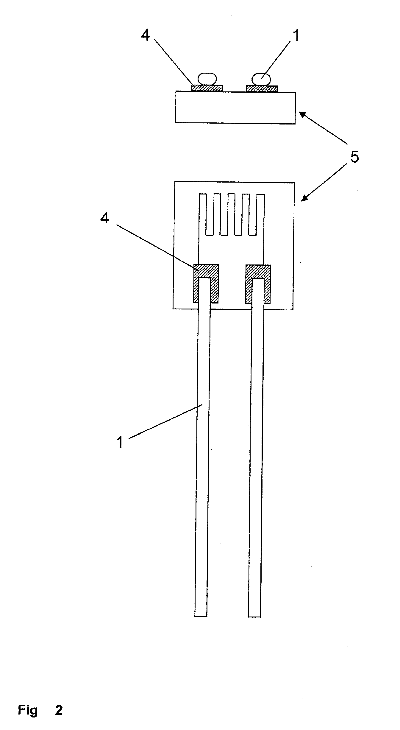
[0008]According to the invention, connection wires are provided having a nickel core and a silver coating. The connection wire having a silver coating according to the invention can be soldered directly to the coating, wherein the contact point suffers no loss in quality of the connection wire due to alloy formation between the silver and nickel. Thus, the production of film resistors of high quality is significantly simplified.
[0021]According to one embodiment of the invention, it is possible to partition by fracturing several film resistors glazed together. This simplifies the production of film resistors made of at least one resistor pattern on an electrically insulating surface of a substrate having a covered resistor pattern and having connection wires strain relieved with glass, which connection wires are connected to the resistor pattern in an electrically conductive way.
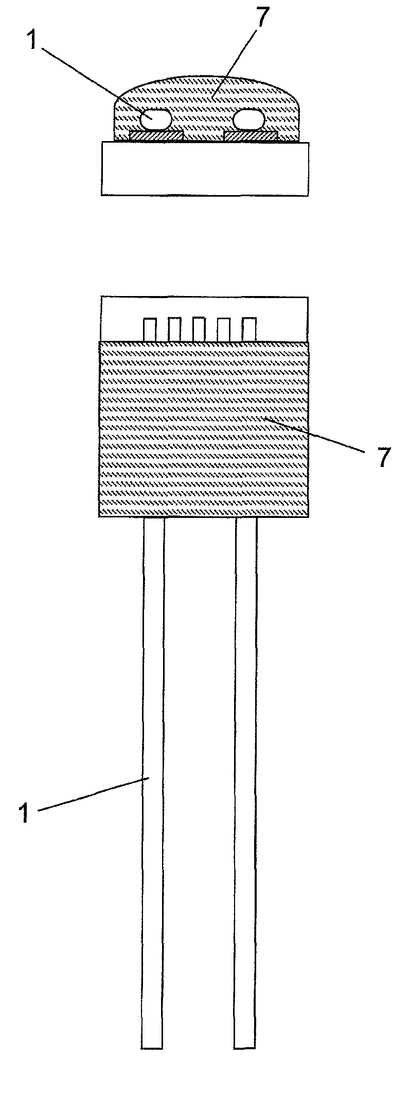
[0022]In a preferred embodiment, the silver wire attached to the contact point is surrounded with glass, in particular using thin-film technology. Then, according to the invention only the wire surrounded with glass is strain relieved by deposition and firing of a glass paste. With this technique, the known bubble formation in the use of glass for strain relief of the connection wires is avoided.
[0023]In an especially simple embodiment, nickel wires according to the invention are provided with a glass coating. The glass coating protects the wires from corrosion and allows bubble-free fixing for strain relief with a glass paste. With the thin glass film, oxide films of the solder point are more easily scratched or broken. The later solder point is in itself comparable to a cermet mixture and, in the region of the solder point, is less sensitive to stresses occurring due to the different coefficients of expansion than the classic metallic solder connections strain relieved with an outer glass bead.

Problems solved by technology

Construction in single units is expensive for mass production.

Method used


Image

  • Coated wire and film resistor
  • Coated wire and film resistor
  • Coated wire and film resistor

Examples


Embodiment Construction

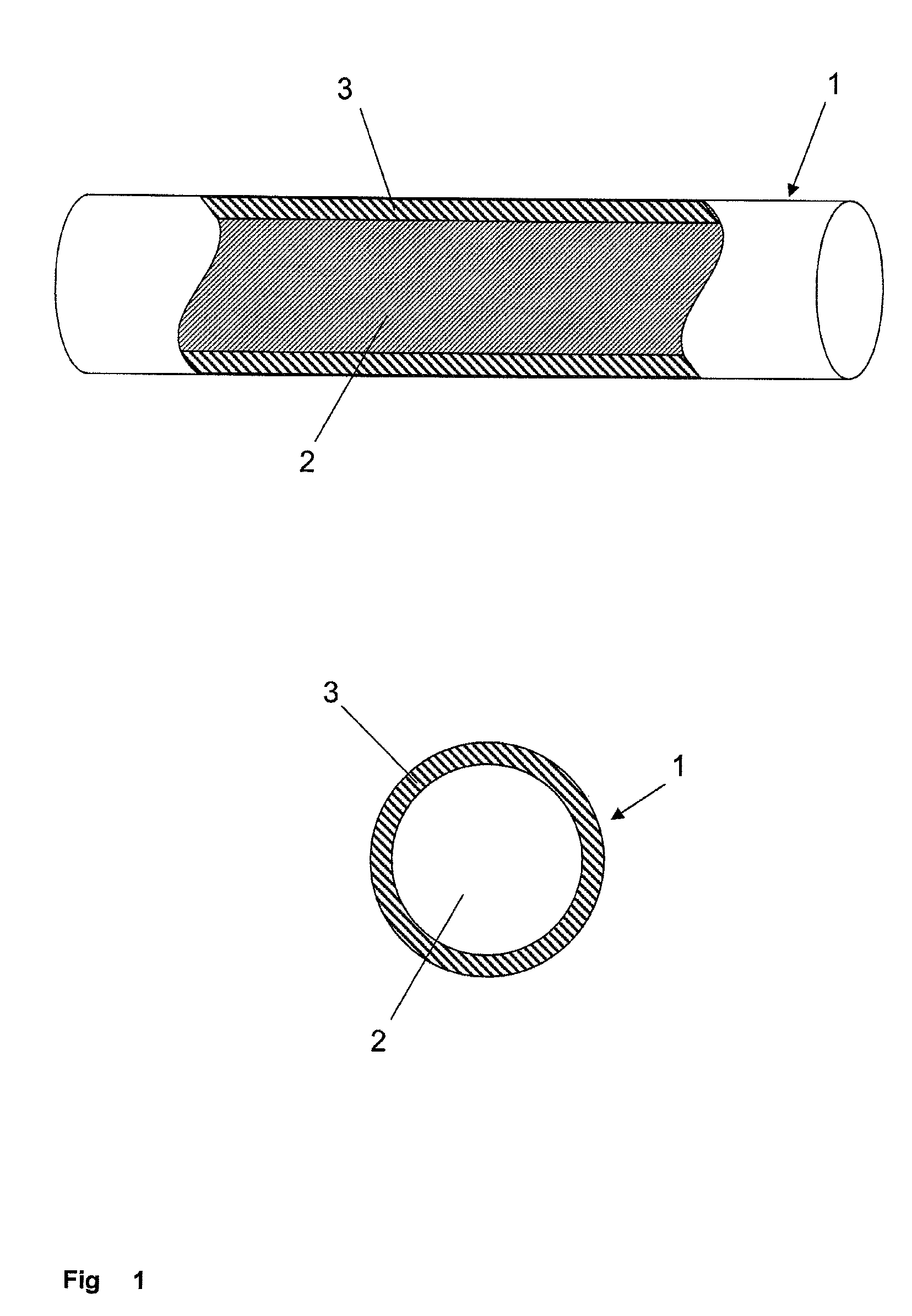
[0031]The quality of a coated wire 1 according to FIG. 1 having a nickel core 2 and a silver coating 3 is not lessened by formation of intermetallic phases, either during the production process of the wire or the film resistor or during the use of the film resistor, because silver and nickel do not tend to form intermetallic phases with each other. The formation of intermetallic phases is a frequently observed problem at solder points and is avoided according to the invention. Problems include, in particular, on the one hand, the increasing material fatigue due to phase growth and, on the other hand, the decreasing conductivity. With the wire according to embodiments of the invention, these problems do not occur. The problems also do not occur when the coating 3 has additionally glass or ceramic or is made only of glass or ceramic or a mixture of these materials. Here, the coated wires 1 according to the invention differ from conventional platinum-nickel wires, in which the nickel d...


PUM

PropertyMeasurementUnit
diameteraaaaaaaaaa
diameteraaaaaaaaaa
temperatureaaaaaaaaaa

Abstract

A coated wire is solderable with soft solder while maintaining separate phases of the core and the coating. A 100 μm to 400 μm thick nickel wire may be coated galvanically with silver. For a film resistor with coated wires as connection wires, including a platinum measurement resistor on an electrically insulating substrate and connection wires connected to the measurement resistor, the connection wires have a coated nickel core. The coating may be made of silver or glass or ceramic or a mixture of these materials, or on its outside may be made of glass or ceramic or a mixture of these materials. For producing film resistors a thin metal or glass component is deposited on a connection wire connected to a track conductor arranged on an electrically insulating substrate, and a thick glass paste is deposited and fired on this metal or glass component. For mass production of film, several film resistors encased together in glass may be partitioned by fracturing.

Description

BACKGROUND OF THE INVENTION[0001]The present invention relates to film resistors, a method for their production, and also novel connection wires made of nickel for film resistors. Film resistors in the sense of the present invention comprise a resistive pattern on an electrically insulating surface of a substrate, wherein the resistive pattern is covered with a glass cover and is electrically connected with connection wires, wherein the connection wires project out from the glass cover.[0002]In particular, the connection wires are mechanically fixed to the glass cover. The glass cover is formed by the deposition of glass paste and its firing on the substrate. Construction in single units is expensive for mass production. If several film resistors are encased with glass together on a common substrate, the film resistors can then by partitioned by sawing.[0003]According to the Heraeus brochure “Ceramic and glass measurement resistors / film resistors / test resistor thermometers” (PTM-W2)...

Claims


Application Information

Patent Timeline
Patent Type & Authority Patents(United States)
IPC IPC(8): H01C1/012
CPCG01K7/183H01B1/02H01C7/00H01B3/004Y10T29/49098H01C17/00H01C17/28
Inventor ZINKEVICH, MATSVEI
Owner HERAEUS NEXENSOS GMBH
Learn More