
Community antenna system in the closed loop mode and the method thereof

a closed loop, community technology, applied in the direction of antennas, diversity/multi-antenna systems, antennas, etc., can solve the problems of reducing system throughput, system efficiency decrease, and inability to obtain corresponding diversity gain, so as to achieve the effect of unified terminal design

Active Publication Date: 2012-03-13
CHINA MOBILE COMM GRP CO LTD
View PDF9 Cites 0 Cited by
  • Summary
  • Abstract
  • Description
  • Claims
  • Application Information

AI Technical Summary

Benefits of technology

This solution allows for seamless integration of smart antenna and MIMO / MISO systems, achieving sufficient transmission diversity and array gains, and facilitating smooth evolution of future antenna systems without large-scale reconstruction, while ensuring efficient use of resources and terminal design unification.

Problems solved by technology

In the solution of simply dividing all of the antenna array elements in the original smart antenna system into two groups, only a two-antenna system in a broad sense is formed from the original antenna array elements, but there still exists a very strong dependency between these two broad-sense antennas, and the corresponding diversity gain cannot be obtained.
This relates to the allocation of the antennas and the public channel resources among different systems, thus causing the decrease of the system efficiency, thereby causing the decrease of the system throughput.

Method used


Image

  • Community antenna system in the closed loop mode and the method thereof
  • Community antenna system in the closed loop mode and the method thereof
  • Community antenna system in the closed loop mode and the method thereof

Examples


embodiment 1

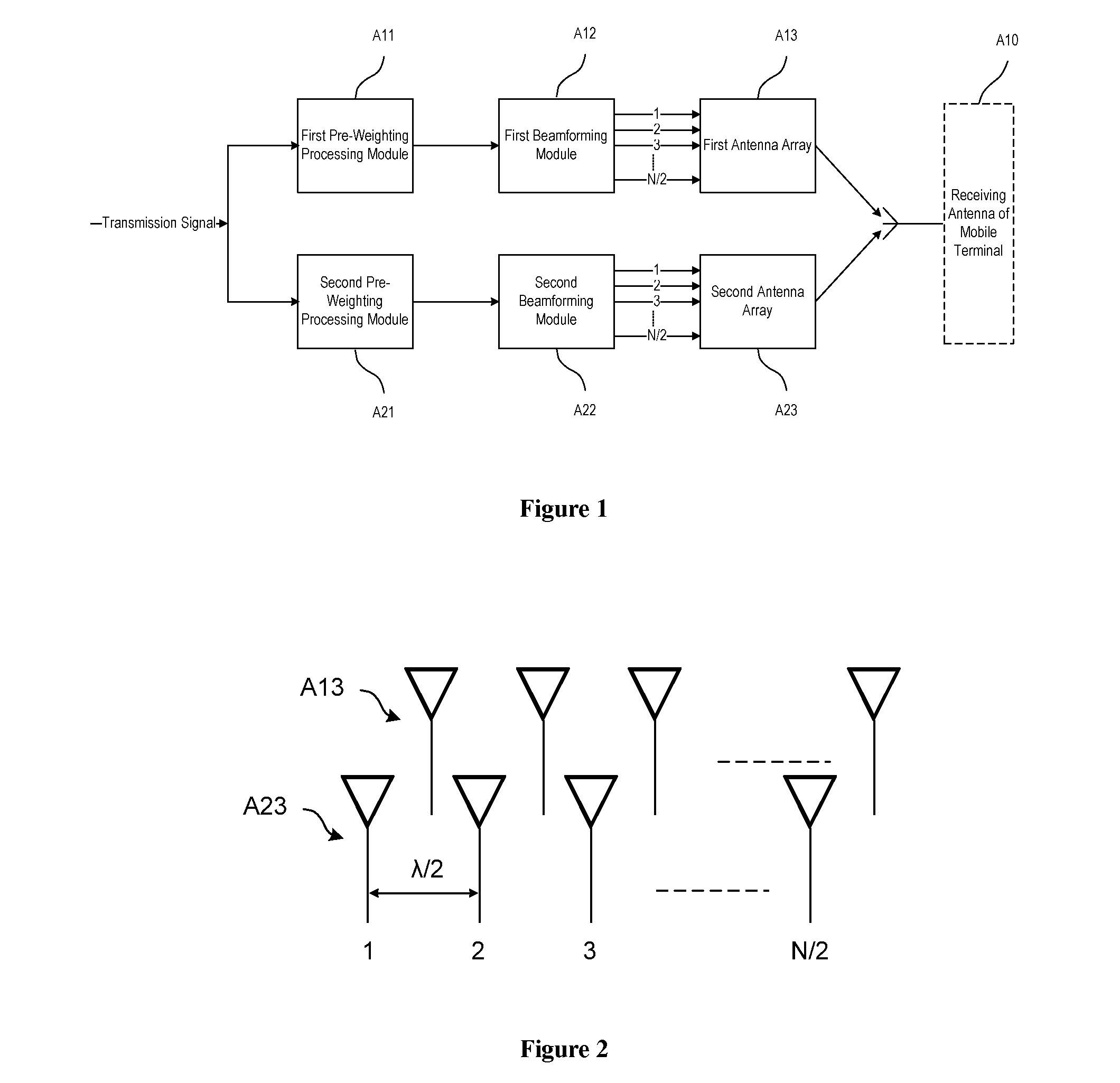
[0090]FIG. 1 is a structural representation of a community antenna system in a closed loop mode when a mobile terminal has a single antenna according to Embodiment 1 of the invention. As shown in FIG. 1, the community antenna system in the closed loop mode is consisted of a first subsystem and a second subsystem that transmit directional beams to a receiving antenna A10 of the mobile terminal. The first subsystem includes a first pre-weighting processing module A11, a first beamforming module A12 and a first antenna array A13 connected in turn; the first pre-weighting processing module A11 is adapted to perform the first pre-weighting processing on a transmission signal according to the first channel information corresponding to the first antenna array A13; the first beamforming module A12 is adapted to determine a beamforming weight vector according to the first group of steering vectors corresponding to the first antenna array A13, and perform the weighting processing on the first...

embodiment 2

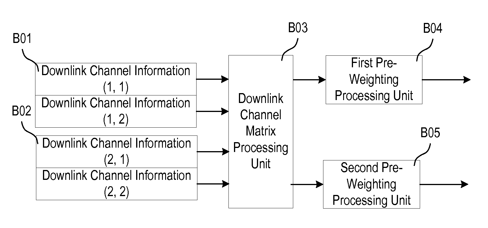
[0115]FIG. 6 is a structural representation of a community antenna system in a closed loop mode when a mobile terminal has multiple antennas according to Embodiment 2 of the invention. As shown in FIG. 6, the community antenna system in the closed loop mode includes a downlink channel matrix processing module B0, a first beamforming module B12 that transmits a downlink directional beam to M receiving antennas B10 of a target mobile terminal via a first antenna array B13, and a second beamforming module B22 that transmits a downlink directional beam to M receiving antennas B10 of the target mobile terminal via the second antenna array B23. Where, the downlink channel matrix processing module B0 is adapted to perform the pre-weighting processing on a transmission signal according to the first group of downlink channel information corresponding to the first antenna array B13 and the second group of downlink channel information corresponding to the second antenna array B23; the first be...


PUM


Abstract

A community antenna system in a closed loop mode and a method thereof are provided, the system includes two groups of pre-weighting processing modules, beamforming modules and antenna arrays connected in turn. The method includes the following processes: performing the pre-weighting processing on a transmission signal respectively according to the channel information corresponding to each of two antenna arrays; determining beamforming weight vectors according to two groups of steering vectors corresponding to the two antenna arrays, and performing weighting processing on the two pre-weighting processed transmission signals respectively to form two directional beams directed to the receiving antenna of a target mobile terminal; and transmitting the two directional beams via two antenna arrays with orthogonal polarization modes respectively.

Description

[0001]This application is a Continuation-in-Part of International Application No. PCT / CN2008 / 001069 filed May 30, 2008 which claims priority to Chinese Patent Application No. 200710099978.8 filed Jun. 1, 2007, both applications are incorporated herein by reference in their entireties.FIELD OF THE INVENTION[0002]The present invention relates to multi-antenna technologies, and in particular, to a community antenna system in a closed loop mode and a method thereof.BACKGROUND OF THE INVENTION[0003]The smart antenna technology has become one of the most attractive technologies in the mobile communications, and has been widely used in a Time Division-Synchronous Code Division Multiple Access (TD-SCDMA) system in a 3G mobile communication system.[0004]The key technology of the smart antenna is the beamforming, which changes the directional diagram of an antenna array according to a steering vector of a signal and generates a spatially directional beam, thereby attaining the object of extra...

Claims


Application Information

Patent Timeline
Patent Type & Authority Patents(United States)
IPC IPC(8): H01Q3/01
CPCH04B7/10H04B7/0615H04B7/0469H04B7/0617H04B7/0626
Inventor XU, XIAODONGLIU, GUANGYICUI, CHUNFENGYAN, ZHIGANGHUANG, YUHONG
Owner CHINA MOBILE COMM GRP CO LTD
Learn More