
Gas dynamic spray gun

a spray gun and dynamic technology, applied in the field of portable gas dynamic spray guns, can solve the problems of low durability of the convergent and throat portions of the nozzle, the attendant malfunction of the spray gun, and the injection of powder into the heated main gas stream, so as to improve the deposition efficiency of the spray gun and improve the efficiency of the effect of efficiency

Active Publication Date: 2012-03-13
TESSONICS CORP
View PDF23 Cites 9 Cited by
  • Summary
  • Abstract
  • Description
  • Claims
  • Application Information

AI Technical Summary

Benefits of technology

"The present invention is a portable gas dynamic cold spray gun that improves efficiency and control by measuring and adjusting powder flow rate and gas flow rate in real-time. This eliminates limitations of prior art spray guns and allows for precise deposition of material. The spray gun includes a gas passageway, powder feed passage, and powder flow rate sensor that measures the powder flow rate and adjusts the gas and powder flow rates accordingly. The technical effects of this invention include improved efficiency, control, and precision in spray deposition."

Problems solved by technology

One difficulty associated with some of the prior art spray systems is that the powder is injected into the heated main gas stream prior to passage through the nozzle.
The powder has a tendency to plug a throat of nozzle to result in backpressure and attendant malfunction of the gun.
The second difficulty is associated with low durability of the convergent and throat portions of nozzle.
Because the heated main gas stream is under high-pressure, the injection of the powder also requires high-pressure powder delivery systems, which are quite expensive and would be difficult to use in a portable cold spray gun.
This type of system has certain problems with control and uniformity of the powder feed rate.
One such problem is pulsation, apparently due to a pressure oscillation, resulting in uneven coating layers.
Another problem with some of the known spray guns relates to the heating unit for heating the carrier gas prior to the nozzle.
Generally, the heating unit is either too large to be used in a portable spray gun, or it is too small to heat the carrier gas sufficiently.

Method used

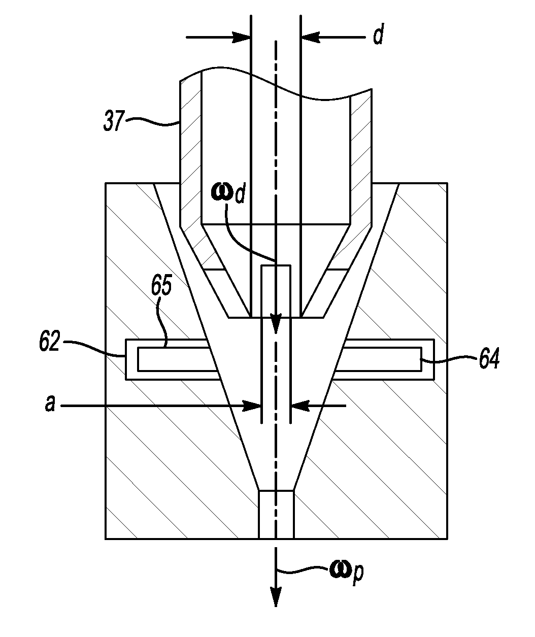
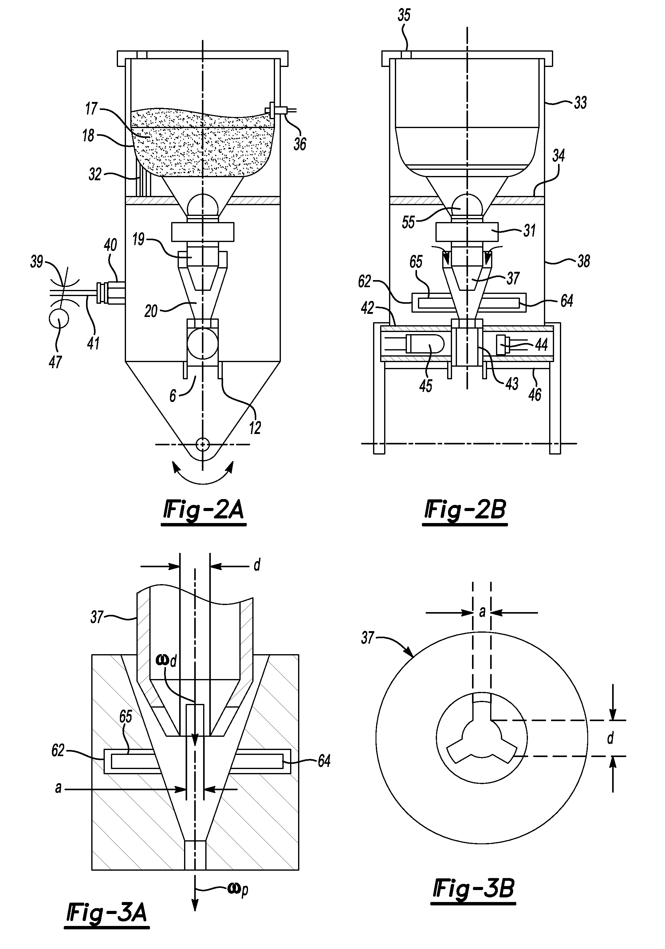

Image

  • Gas dynamic spray gun
  • Gas dynamic spray gun
  • Gas dynamic spray gun

Examples


Embodiment Construction

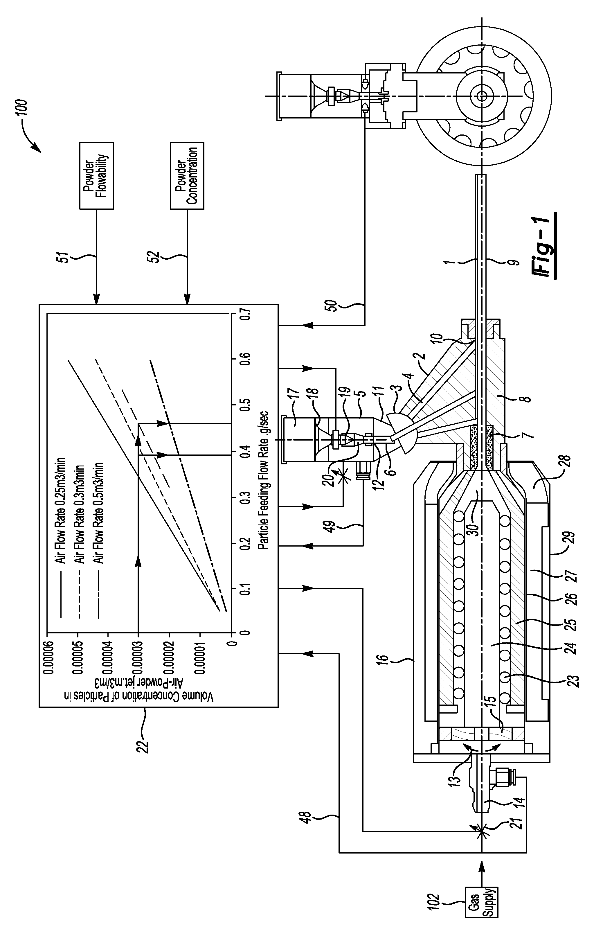
[0019]A portable gas dynamic spray (GDS) gun 100 according to the present invention is shown in FIG. 1. The GDS gun 100 generally includes a pressurized gas source 102 supplying high-pressure air or other gas to a heat chamber 16. A ceramic insert 7 leads from the heat chamber 16 and forms the throat and part of the converging portion of a nozzle. A steel tube 9 leading from the ceramic insert 7 forms the diverging portion of the nozzle. The tube 9 extends through an outer housing 2 from which it is supplied with powder 17 from a container 18. Generally, as the pressurized air or other gas passes through the nozzle, it reaches supersonic velocities and draws powder 17 from the container 18 into the tube 9.

[0020]The outer housing 2 has multiple passages 4 therethrough each leading to axially-spaced orifices 10 on the tube 9. A rotatable switch 3 selectively supplies powder to one of the multiple passages 4 in the outer housing 2 based upon the value of negative pressure at certain po...


PUM

PropertyMeasurementUnit
temperatureaaaaaaaaaa
flow rateaaaaaaaaaa
temperatureaaaaaaaaaa

Abstract

A portable gas dynamic cold spray gun eliminates many of the inherent limitations of the prior art by minimizing a scatter of operating parameters and improving its efficiency. According to one feature of the present invention, the powder flow rate is continuously measured so that the powder flow rate and / or the flow rate of the pressurized gas can be adjusted accordingly in order to control the deposition efficiency of the spray gun.

Description

BACKGROUND OF THE INVENTION[0001]This invention relates to a portable gas dynamic spray gun for cold gas dynamic spraying of a metal, alloy, polymer or mechanical mixtures thereof.[0002]Gas dynamic spray guns coat substrates by conveying powder particles in a carrier gas at high velocities and impacting the substrate to form the coating. The gas and particles are formed into a supersonic jet having a temperature below the fusing temperature of the powder material, and the jet is directed against an article to be coated.[0003]One difficulty associated with some of the prior art spray systems is that the powder is injected into the heated main gas stream prior to passage through the nozzle. The powder has a tendency to plug a throat of nozzle to result in backpressure and attendant malfunction of the gun. This requires a complete shutdown of the system and cleaning of the nozzle. Larger particles tend to plug the nozzle even more.[0004]The second difficulty is associated with low dura...

Claims


Application Information

Patent Timeline
Patent Type & Authority Patents(United States)
IPC IPC(8): B05B1/24
CPCB05B7/1422B05B12/085C23C24/04
Inventor MAEV, ROMAN GR.LESHCHYNSKY, VOLFSTRUMBAN, EMIL E.
Owner TESSONICS CORP
Learn More