
Method of controlling criticality of nuclear fuel cycle facility, method of producing uranium dioxide powder, reactor fuel rod, and fuel assembly

a criticality control and nuclear fuel cycle technology, applied in the direction of nuclear elements, greenhouse gas reduction, uranium compounds, etc., can solve the problems of increasing cost, reducing economic efficiency, and reactivity loss of a reactor core, so as to reduce the impact of criticality control, increase economic efficiency, and reduce the cost of fuel cycl

Active Publication Date: 2012-03-06
KK TOSHIBA
View PDF6 Cites 0 Cited by
  • Summary
  • Abstract
  • Description
  • Claims
  • Application Information

AI Technical Summary

Benefits of technology

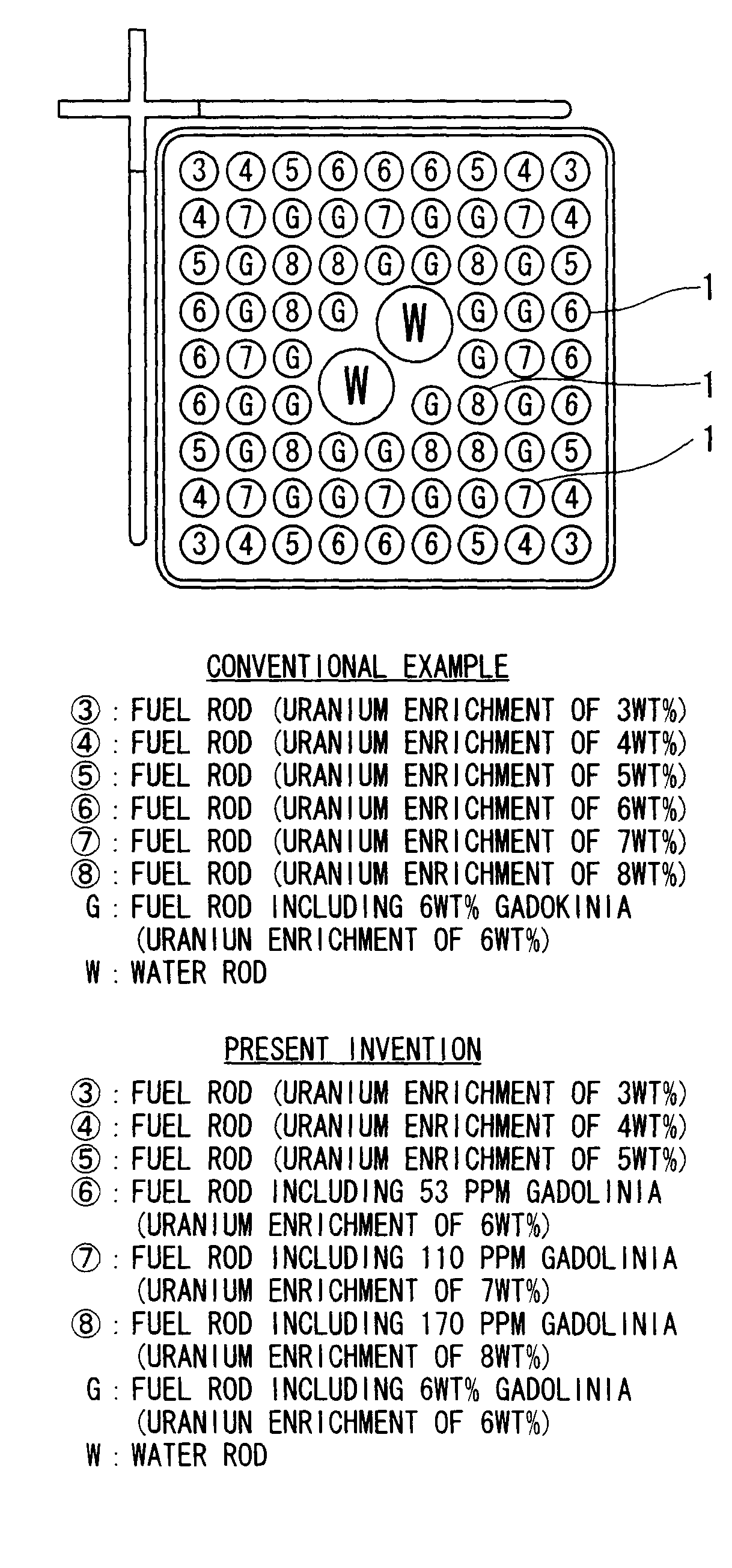
The present invention provides a method for controlling the criticality of a nuclear fuel cycle facility and producing uranium dioxide powder with a reduced impact on criticality control. This is achieved by adding a small amount of gadolinia to uranium dioxide powder with a high uranium enrichment. The method includes steps of controlling the effective neutron multiplication factor of the uranium dioxide system and optimizing the uranium enrichment of the reactor fuel. The invention also provides a method for producing uranium dioxide powder with a reduced amount of gadolinia. The invention also includes a reactor fuel rod with a reduced amount of gadolinia and a fuel assembly for a light-water reactor with improved safety and efficiency.

Problems solved by technology

In order to use the reactor fuels with a uranium enrichment of greater than 5% by weight, such design changes and / or equipment modifications required for each step cause an increase in cost, and therefore, may offset the reduction in fuel cycle costs due to the increase in the enrichment of reactor fuels as described above.
If a burnable poison is added to a reactor fuel, the burnable poison remains in the reactor fuel at the end of an operation cycle depending on the type of the burnable poison and therefore may cause the reactivity loss of a reactor core.
Hence, it is difficult to achieve the reduction in fuel cycle costs due to the increase in the enrichment of reactor fuels.

Method used


Image

  • Method of controlling criticality of nuclear fuel cycle facility, method of producing uranium dioxide powder, reactor fuel rod, and fuel assembly
  • Method of controlling criticality of nuclear fuel cycle facility, method of producing uranium dioxide powder, reactor fuel rod, and fuel assembly
  • Method of controlling criticality of nuclear fuel cycle facility, method of producing uranium dioxide powder, reactor fuel rod, and fuel assembly

Examples


first embodiment

[First Embodiment]

[0059]A method of controlling the criticality of a nuclear fuel cycle facility according to a first embodiment of the present invention will now be described with reference to FIGS. 4 and 5.

[0060]Non-patent Document 2 specifies “minimum estimated criticality values” and “minimum estimated criticality lower-limits” that are constraints used in “mass control” not handling any reactor fuel having a mass exceeding a limit on criticality control or “geometry control” not handling any reactor fuel having a size exceeding a limit on criticality control with respect to a uniform UO2-H2O system that is the strictest model on criticality control in consideration of “complete submergence”. Table 1 shows constraints used in a UO2 powder-handling step (hereinafter referred to as a UO2 powder step). The term “estimated criticality value” used herein means such a value that something having a mass or size equal to the value is determined to be critical. The term “estimated critic...

second embodiment

[Second Embodiment]

[0076]A method of producing a UO2 powder according to a second embodiment of the present invention will be described hereunder with reference to FIGS. 6 to 8.

[0077]In order to produce a reactor fuel from the UO2 powder, a burnable poison is uniformly added to the UO2 powder. Therefore, the reactivity-suppression effect of the burnable poison can be used in a step of handling the UO2 powder.

[0078]FIG. 6 is a flowchart showing a conventional method of producing a UO2 powder through the reconversion of uranium hexafluoride (UF6) by a solvent extraction process.

[0079]As shown in FIG. 6, UF6 is added to an aqueous solution of aluminum nitrate, an aqueous solution of uranyl nitrate is thereby prepared. Ammonia is added to the aqueous uranyl nitrate solution, ammonium diuranate (ADU) is thereby precipitated, and the obtained precipitate is dehydrated, roasted, and then reduced, thus producing the conventional UO2 powder.

[0080]FIG. 7 is a flowchart showing the method of t...

third embodiment

[Third Embodiment]

[0084]A reactor fuel rod according to a third embodiment of the present invention will be described hereunder with reference to FIG. 9.

[0085]FIG. 9 is a schematic sectional view of the reactor fuel rod 1.

[0086]The reactor fuel rod 1 includes a cylindrical fuel cladding tube 2 including: a lower-end plug 3 welded to the lower end thereof; cylindrical fuel pellets 4 which are packed in the fuel cladding tube 2 and which are made from a UO2 powder containing a slight amount of gadolinia; a plenum spring 5, placed in an upper hollow portion of the fuel cladding tube 2, for pressing the fuel pellets 4; and an upper-end plug 6 welded to the lower end of the fuel cladding tube 2.

[0087]The UO2 powder contains, for example, less than 0.1% by weight of gadolinia. The fuel pellets 4 are produced by sintering the UO2 powder. In particular, the UO2 powder is pressed into blanks with a predetermined shape. The blanks are heat-treated in a reducing atmosphere so as to be sintered...


PUM


Abstract

A method of controlling the criticality of a nuclear fuel cycle facility includes steps of producing a reactor fuel by adding less than 0.1% by weight of gadolinia to a uranium dioxide powder with a uranium enrichment of greater than 5% by weight and controlling the effective neutron multiplication factor of a uranium dioxide system in a step of handling the reactor fuel to be less than or equal to the maximum of the effective neutron multiplication factor of a uranium dioxide system with a uranium enrichment of 5% by weight.

Description

BACKGROUND OF THE INVENTION[0001]1. Field of the Invention[0002]The present invention relates to a method of controlling the criticality of nuclear fuel cycle facilities, a method of producing uranium dioxide powders (UO2 powders) that are reactor fuels (UO2), a reactor fuel rod loaded in a nuclear reactor, and a fuel assembly. The present invention particularly relates to a method of controlling the criticality of a nuclear fuel cycle facility, such as a fuel fabrication facility or a fresh-fuel storage facility, using a reactor fuel rod fabricated using a UO2 powder containing less than 0.1% by weight of gadolinia (Gd2O3), to a method of producing a UO2 powder, to a reactor fuel rod, and to a fuel assembly. Furthermore, the present invention covers a method of controlling the criticality of a spent-fuel transport / storage cask or a fuel storage pool for storing the fuel assembly.[0003]2. Related Art[0004]In order to enhance the power uprating and operation period extension of nucle...

Claims


Application Information

Patent Timeline
Patent Type & Authority Patents(United States)
IPC IPC(8): G21C3/00
CPCC01G43/00G21C3/623G21C21/02G21C7/04Y02E30/38Y02E30/39Y02E30/30
Inventor WATANABE, SHOICHIMITSUHASHI, ISHIYOSHIOKA, KENICHI
Owner KK TOSHIBA
Learn More